You want me to feed it bigger bullets? Until it dies? Aw man that’s harsh! It’s such a pretty little thang!
The Efest IMR10440 delivers 3A routinely. I use em in my MBI HF’s that are direct drive to XM-L2’s. I’ve got almost a dozen of em. (cells, I mean, only 3 HF’s, of which I EDC 2 and the TP which also uses an IMR10440)
I, uh, well, I’ve got this 14500 high discharge cell that can probably fry the lil dude. I’ve got an AW IMR14500. Also an Int Outdoors protected 14500, and then I’ve got bigger fodder…
Ok, Ok, I’ll go run the 4.20V Efest IMR10440 through it, see what it says at full charge. BRB…
I had only done output measurements on my LZZ-06 build sofar, I just did a current measurement with a full Efest 10440 battery held against the head: 3.45A on high
I took it up to 4.23A with an AW IMR14500, is that enough? .02, .32, 2.00, 4.23A And with subsequent runs, letting each mode sit in use for several seconds at least, it did about the same. Started getting a little lower as the cell pulled down but yeah. It’s up there. The IMR14500 was at rest at 4.08V.
Should I try the bad ass 14500? Or even bigger cells? I probably have something that will fry it, with Sony C4, C5, Efest 35A, Samsung 20R and 25R on hand.
A protected 18500 AW cell gave me .02, .26, 1.64, and 3.58A
The protected Intl Outdoor 14500 did .02, .29, 1.56, and 3.15A
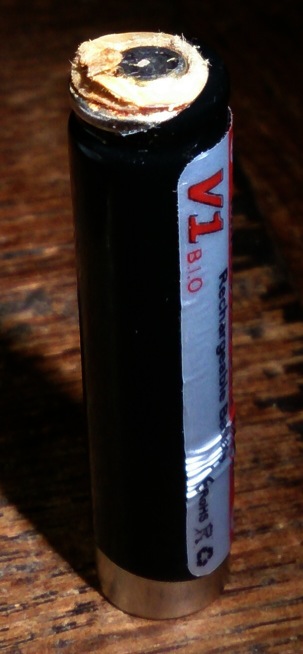
Slightly off-topic: those Efest 10440 cells can do not stand endless torture, after 5 minutes at high on my little LZZ-06 BLFtiny12-FET build initially it looked like only the shrink-wrap had suffered from the heat, now a few days later brownish gooey came out pulverising the paper disc on top, it still works though...
I ran an Efest IMR18650V2 through it for .02, .34, 1.63, and 4.15A
So then I ran my badass 14500 charged to 4.19V through it and it did .02, .35, 2.16, and 4.52A.
Wanting to see what else she could handle, I broke out the Samsung 25R charged to 4.17V. It did .02, .38, 2.34, and 5.13A. Seems to me it’s pretty capable of pretty much any cell I have.
How hard is it likely to be pushed in the lights in which it will be used? I think we’re already past that but you know you want to find the ceiling first. Push it ’til it fails or set that board aside and make another to kill. Chips are cheap, much cheaper than an equivalent number of 7135’s.
Scott, I’m betting the only thing that could kill that 10440 is a combination of all things evil…high current draining it to very low levels while heating it to boiling point. 5 minutes under an FET driver is brutal for that small cell. But, djozz DID say it still works!
I do not know for sure, my first reflex is: high heat, the light got so hot that I burnt my fingers twisting it off. but it had been running at 2+ amps for most of the five minutes by then.
It is indeed important to know what these lights are capable of, but it’s difficult to go by my findings if I manage to fry it cause I do all kinds of other things wrong. Nature of the beast and all that.
But you know, if it can put out over 5A then I’m going to be pretty happy with it just under 3A. Might even have to change some things in the firmware to limit it to say 80% or something, just so it doesn’t hit those really high numbers.
If this is a FR4 PCB, I would like to suggest you to put at least 20 thermal vias on the pour copper and near the both sides of the LED’s thermal pad.
The recommended thermal vias size by Cree is 0.3mm diameter. Here enclosed the Cree’s FR4 thermal study for LED. Dropbox - XLamp_PCB_Thermal.pdf - Simplify your life
PC = phase correct (9.4kHz, 'TCCR0A = 0x21'), FP = fast PWM (19kHz, 'TCCR0A = 0x23'). Levels for both are 0,2,6,18,54,130,255. Both turn on and off and change modes exactly like they should. The phase correct board makes a slight whine on level 4, moderately loud whine on level 5. Fast PWM board is silent.
Why do these boards work fine without the gate/pulldown resistors? These are the exact same components used on the 17DD, which does not work without the resistors.
Thus I think STAR V1.1 and a timeout is the safest way to go
And/or have a approx 50% PWM always on…this way you don’t just run it wide open, I wouldn’t use that battery, it has vented…just not “explosively” yet!
Being an IMR battery it is unlikely to vent explosively, obviously something has happened to it, but it just now was still able to deliver 3.5A to the light. But I guess you are right, I will stop using the battery and dispose it .
I successfully rewrote my UI! I made a new .hex file for the BLFTiny10 that replaces the 255 Turbo with 190, and the previous High setting with 90. After flashing the little guy I ran it through on the IMR10440 and it does .03, .31, 1.16, and 2.20. Perfect!
My TP has a Nichia emitter in it, don’t think it could’ve handled the full out direct drive. So now I get to try to make a contact pad over the FET and diode and then see if I can put it in my light. This is exciting!


 .
.