LOL ;) I didn't try to make the S6 ultra small, I just tried to get rid of the wasted space in the existing design. It's practically a baseball bat compared to others...


LOL ;) I didn't try to make the S6 ultra small, I just tried to get rid of the wasted space in the existing design. It's practically a baseball bat compared to others...
![]() I was making reference to the fact that the S6 I showed the TP next to wasn’t stock. Probably should have put a stock one next to it, or showed it next to the S2200. lol
I was making reference to the fact that the S6 I showed the TP next to wasn’t stock. Probably should have put a stock one next to it, or showed it next to the S2200. lol
I could’ve shown it next to a mini C8 and made it look big… it’s about the same size as the mini C8 and without looking close it would have looked full size.
Dbcstm, you can clean it up with rubbing alcohol and a toothbrush. B-12 works faster but is much more toxic. Neither seems to affect the solder mask or silkscreen.
I just built the second BLF Tiny10 FET. :bigsmile: It’s running 3.48A to an XM-L2 T6 3C. I’m either going to hook it up to a de-domed XP-G2 R5 1A or a domed XP-G2 R5 3C. Whatdya think?
Yup, all is well I just have been really busy with school and haven't really had the time to get on to BLF. Thanks for asking though.
so I’ve been filling in for you. ![]()
The little 3” Texas Poker is now doing 552 Out the Front lumens at start up, 452 at 30 seconds. Pulling ~3.02A from an Efest IMR10440. ![]() De-domed XP-G2 R5 1A.
De-domed XP-G2 R5 1A.
BLF Tiny10 FET with 22 ga Silicone wires. No limits in the firmware.
Nice! I did get access to some lab power supplies so I have been playing around with XM-Ls at sub-zero temperatures (peltier plates and dry ice); it got brighter all the way up to 9 amps. ![]() Someday I’m gonna get set up to measure lumens and redo that experiment and see how many lumens I can hit with an XM-L.
Someday I’m gonna get set up to measure lumens and redo that experiment and see how many lumens I can hit with an XM-L.
(nice to see you still around every now and then) I would not mind a post about that with a picture of the set-up, nice tests! :-)
Once I'm set up to do it in a more scientific manner I will make a post about it.
That pushing those amounts of lumens has GOT to be getting hot really fast…but still…a complete sleeper
It’s got all the copper it can have and still be silver in color.
I’m thinking at this rate we’re gonna need another gb on more of them. Matt hasn’t even got his and I’m all out.
Always glad to see you Scaru. Yours have been some of the most helpful threads here.
It's pretty much done, so I may as well upload the redesigned board anyway. I'll label it as V2.0. Should be up tonight.
- Matt
No problem, if they work without them the gate resistor can just use a jumper.
Is it possible the longer trace on the SRK board is why those don't need the resistors? I really can't come up with anything that makes sense to explain it. :~
I don’t know about dissolving fiberglass since it’s resin and fiber but you can sand it thinner. The more common way of doing it so far has been to drill or machine out the center pad and replace it with copper.
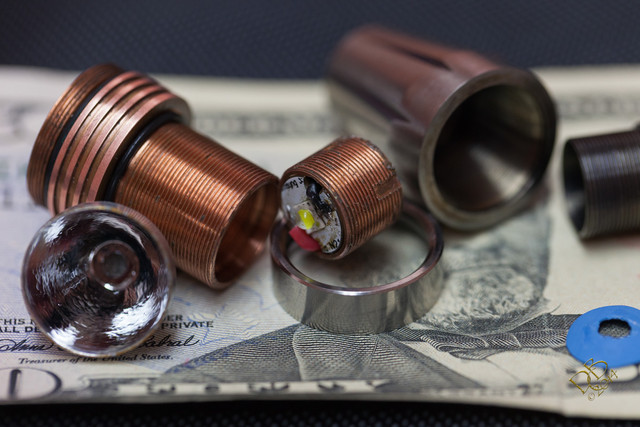
I’m amazed at how close the components can be on the driver and not have issues. Some are difficult to see if they’re not touching, they’re that close. And yet some pretty major amperage runs through the circuits and all is well, and with these little bitty drivers the traces just can’t be all that big…is 22ga wire from the driver to the emitter overkill? I had to stuff the wires into the TP pill, even had to pull em through with my curved jaw hemostats, they just do fit, like everything else on this driver. ![]()
Most of the traces only carry signal currents and on the Tiny 10 the trace length to the led pads is practically nothing. Led + is straight through the board with no trace, led- is less than 1mm and gnd is a wide tab. Lately this subject has received more attention and an effort has been made on some of the new project boards to make sure of adequate trace width. If you think it’s necessary you could scrape the solder mask from the drain trace and when you solder the FET or 7135 it would flow to the - via. If it is an issue then that trace width could be increased but that driver wasn’t designed with 10A currents in mind. Wire size is a different matter due to increased length but at 2A awg24 will only drop .017V in 1/10 foot(1.2”).
Mine’s working fine and I’m loving it! ![]() Was just stating how impressive they are.
Was just stating how impressive they are.
And yeah, keeping the battery size in line with the driver size there seems to be little to no issue of power handling. 3A with a fresh IMR10440 is ample, and of course that falls with the deteriorating charge level. On a positive note, the more the cell drains the slower it drains, right? lol
Seems to me that with the way mine’s running, Turbo should deliver around 15 minutes, High should make about 30 minutes, Med around an hour and Low around 10 hours. Give or take.
That being said, ain’t no way it’s gonna run 15 minutes on high! Something would melt…
Just letting you know that 22 is a bit of overkill but if it fits no harm done. You’d have to go almost 12A to drop .1V in that length of 24 gauge.
I agree completely. No sense trying to stuff huge wires in there when it's only a 1" run. This isn't a bad example of that but I've seen some pictures where people were trying to stuff 18AWG in a 1" run to an XM-L2, not necessary. Even 26AWG doesn't show any appreciable loss at 5A at that short of a run. On the SRK's I really like the 22AWG because there is plenty of room and because the wires have to be so stinking long, on normal lights with the short wires 24-26AWG is just fine, even for hard driven lights.