Sorry if it's obvious but there should be NO noise at 100% PWM...
All good, thanks guys!! Sometimes I think I know this sh#$%, then I realize I know squat, so at this point, some things sound obvious, some are goin right over my head... The terminology can throw me off, and then there's the real details of doing the work - I'll miss something obvious to many others... Ugh.. trials/tribs.
I probably got into the boards too early, more my fault than anyone's. I need way too much hand-holding at this stage. Also, I'm trying to do way too much for what I have time to do. Losing billable hours (pays the bills), way behind on promised mod lights, etc.... I really want to do more, but at my age, I still need some hrs of sleep, otherwise I'm worthless at work (finding that out  ).
).
I've been stay'n with the 9.4 kHz (not the fast-PWM), guess because of the moonlight PWM's.
Yes, for example the version of luxdrv I used for so long has levels of 2,16,84,255. It's only audible at 16 if you hold it close to your ear, but at 84 you can hear it in normal use held out at arm's length.
Tom, the FETs work reliably all the way down to a PWM level of 1, they're not like the 7135s that only start working at 4 or 5.
Yes, understood with the FET's you can go full scale down to 1 PWM - I've been using that feature, but with 7135's, the min PWM value is higher than the standard value of 5 I've been using (4 works flaky). I'm also used to specific PWM values based on phase corrected PWM's, and I thought the output levels scale differently with fast PWM's. All a matter of experimenting I suppose.
I received some of the LFPAK56 FETs from mouser and put one on the test board (standard Qlite firmware with star 4 soldered). After cutting some traces to isolate the drain tab it wasn’t at all difficult to solder. A cheap protected 14500 delivered ~35mA moon and 3.5A high with no pwm noise. Any cell that could deliver more current had unstable modes so I added back in just the gate resistor(no pull down) and this resulted in stable modes. An efest 14650 delivered ~75mA moon and 5.5A high before the led started smoking(obviously I need to upgrade to a copper star for testing high currents) also with no pwm noise in any modes. Both cells were 4.05-4.08V rested. The modes still seem well spaced though it would be nice to have the moon shifted back down to under 10mA. I don’t know if the instability is a firmware issue or not. Someone would have to try the same board with stock and custom firmware to find out but the resistor does seem to alleviate it. The chip easily fits on the board without covering either the ground ring or the wide central pwm trace. Pics of this mod are in the phone and will be posted later tonight.
Qlite firmware is using fast PWM at 19kHz, so it's not going to whine no matter what hardware it's controlling.

Here are the pics of the LFPAK56 FET mod of a qlite 105C driver. I did this for no particular reason other than I wanted to try it and I think it’s a better fit for some instances than the 70N02 FET since it doesn’t have any parts that need to be filed off to fit. Some pills have a lip that might interfere with the larger FET.
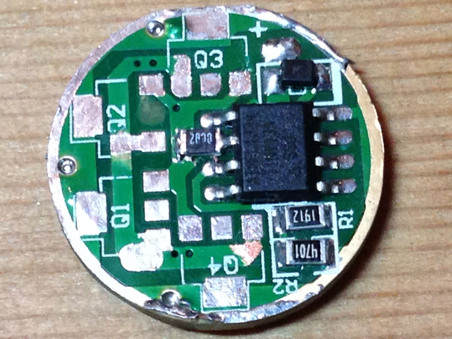
Here is the board cleared of 7135’s. It’s the same one I used to test the irlm2502 FET.
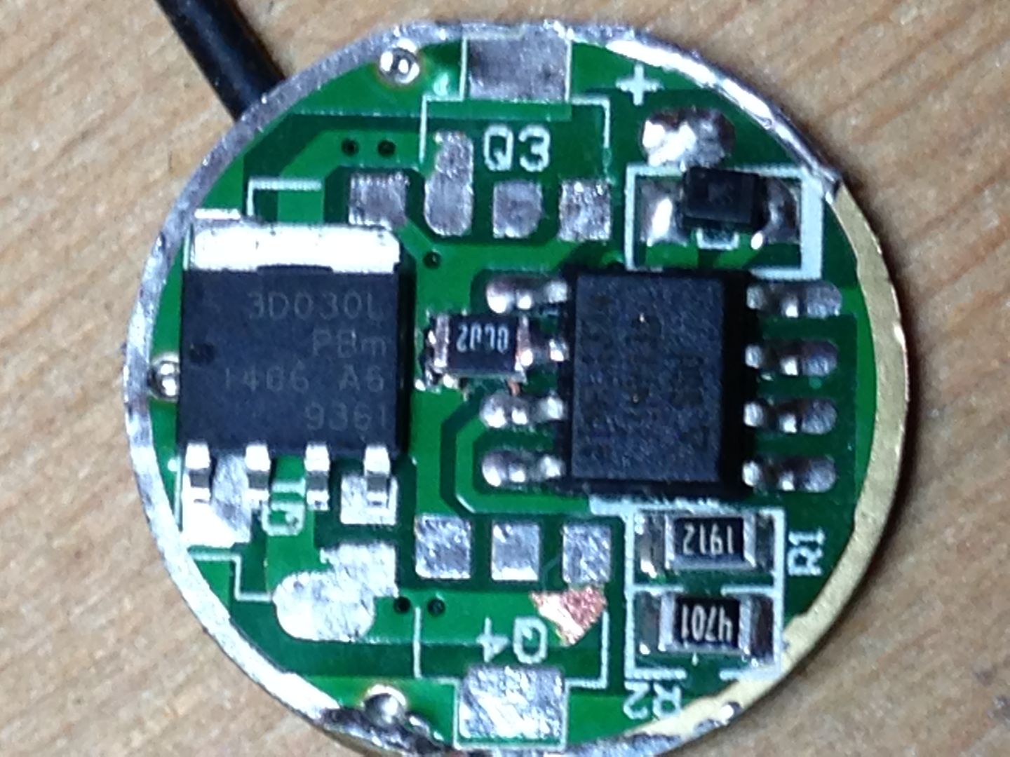
Here is the board with the LFPAK56 FET sitting where I’m going to install it. Most of the bottom of the chip is the drain tab so I’ll need to make cuts through any traces that are used elsewhere. The drain trace where it goes through the board is not a concern as those traces to not connect on the other side. Also, the former ground pin pad is shortened to prevent one of the three ground pins from soldering to two pads and shorting them together.
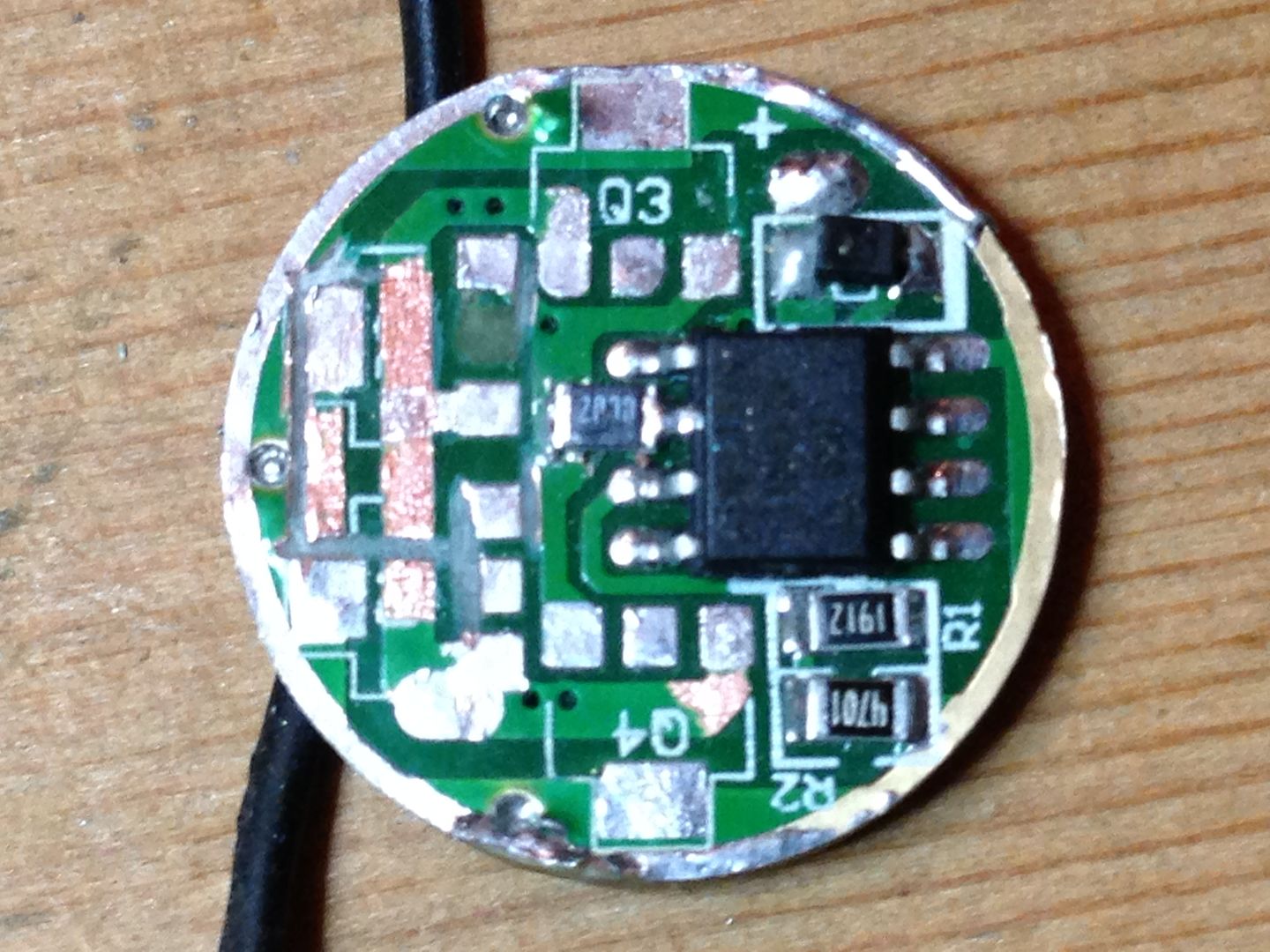
Here is the board with all the traces cut that run under the chip. The drain trace(formerly led-) is cut to prevent a short to ground but left intact elsewhere.
And finally, here it is with the chip and output wire soldered in place. For testing purposes I soldered both Vin+ and led+ to the center pad on the other side. Likewise, ground and led- had wires soldered to them.
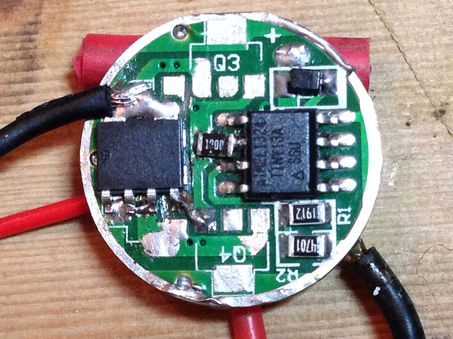
I posted the results of the first test above. Next time at home I’ll switch to a sinkpad and run it with some bigger cells. A mostly full efest 14650 pushed 5.5A through it.
I'll be around in a couple of hours for a lesson. Looks orsm what you have done.
Rufus, pretty cool setup there. I love seeing new options out there, you never know unless you try!
Does it change modes properly without the resistor?
and whine?
If it's still got the stock Qlite firmware on it (or any fast-PWM 19kHz firmware), it's not going to whine. It has nothing to do with the hardware. Even a bone stock 7135 105C will whine (causes the switch to make noise) when using phase correct 9.4kHz firmware.
Both the 2502 and this are stable using smaller cells. The 2502 up to 1.5A and and the LFPAK56 up to 3A don’t need the resistors using the fast pwm but with decent cells both need the 100 ohm resistor for stable modes. I haven’t found what the maximum current is for either but they are rated at 70A and 100A respectively. Dale has sent me a few reflashed mcu’s so I can try these out with hex file you set up Comfychair. I’ll also see what the buzz is on pwm noise. I have to transfer the test led to a 20 mm sink pad as well before I can push them any harder.
Is there a possibility of an intermediate pwm frequency?
I'm not sure that an intermediate frequency would help our situation much, well, maybe not for you old guys who have lost some of your high frequency perception  . Really though, it would probably still be audible until you hit the 18K-19K mark anyways. I'm not sure what the hardware limitations are.
At least I’ll get to experience it firsthand now and try out any ideas that come up.
I just tested my hearing limit last week in schoolclass with the pupils, and above 14kHz I hear nothing, an intermediate frequency would work for me
The SRK board works fine with the silent 19kHz fast-PWM. Why that same firmware doesn't work on the 17mm board using the exact same components unless you add the gate & pulldown resistors, I have no idea. The only difference is the PCB and no matter how many times I go back and compare them, they should be functionally identical, just different sizes.
I hate to say this but maybe size does really matter! :zipper_mouth_face: