Thanks for the info.
Just bought a pack of the switches, at this price I couldn’t resist.
I spent a half hour last night and did a quick polish on the light. This wasn’t a very thorough polish… just enough to get it looking neater than before, but by no means mirror finish.
Before:
 After:
Here’s a picture of the polished light standing next to an unmodded Sipik 68:

And here’s a beamshot showing the Aleto next to a Sipik 68. The Aleto is running on Samsung 25r and the Sipik is running on 14500. The Aleto is enormously brighter, but it’s hard to tell in this beamshot. However, you can clearly see how much wider the floodbeam is compared to the Sipik.

Wonder why the lightning didn’t take out the gold in the machined grooves?
Looks fantastic after the polishing.
Actually it did get the gold out of the grooves between the heatsink fins and the small grooves on the bezel. However, I wasn’t able to easily polish between them with my quick polish job so the area between the fins is a lighter unpolished color grey-white.
The one area that still has some gold is part of the area under the sliding bezel. It’s not visible except when the bezel is extended in spot mode. That was my fault for soaking it in Greased Lightning with the bezel sitting on the body.
Greased Lightning needs room to circulate in order to do a good job removing anodizing.
Great job! I love what you've done with it. These are the kinds of threads that keep me coming back to BLF.
The entire conversion over to an e-switch is amazing! Great job on this light!
Whew!
Tried to do an emitter swap last night.
Turns out I had too much thermal epoxy under the star (I’d held the star on with 2 dabs of arctic silver epoxy at the side and arctic silver 5 thermal grease in the center).
Took an enormous amount of effort to finally get that star off. Destroyed the old emitter in the process too…. oops! Then when I put the new star and emitter in, the light kept failing. Wasn’t sure what the problem was. Took the light apart and actually built an entirely new duplicate driver just on the off chance that was the problem.
Turns out after the effort of trying to get the original star off, when I put in the replacement I wasn’t using enough thermal epoxy. It was failing and the star was separating from the pill. This cause the solder joins from the driver wires to the star to melt and break contact.
I finally fixed it by using more thermal epoxy… hopefully not too much like the first time.
I’m thinking that perhaps this would be a lovely light to actually use screws to hold on the star. I’ve never used screws for stars before, but that would solve the problem completely and be way better than having to torque through a big bunch of epoxy each time.
Yes, screws are nice. If you need to, you can mix some Arctic Alumina with some regular thermal paste, that way you can get good coverage and have a bond that isn't quite as strong.
Good idea.
With my reflector lights, usually the reflector presses down on the star so nothing extra is needed. But with these aspherics, the star is exposed. Definitely something extra needed to keep it in place.
I put on a replacement star with screws…. much better now! :party:
I used a 16mm direct copper star from Illumination Supply instead of a Noctigon. The Illumination Supply star had convenient holes for screws already in the star. I used some leftover screws I had that came with a flashlight clip. I’m quite happy with how it came out. Using 2 screws and a layer of Arctic Silver 5 thermal grease I’m getting much better thermal conductivity than with thermal epoxy.
Anyone know a good source to get more tiny screws? I have other lights I’d like to do this to.
Home Depot! Really, it depends on the quantity, sizing, and quality you need. Usually there are local "nut and bolt" supply houses that have a huge selection. Online there's always McMaster-Carr.
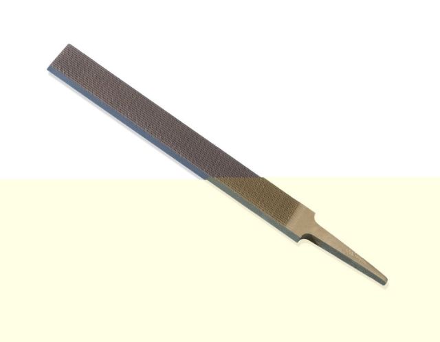
My checkering file from Amazon arrived.

The face of the file is a set of pyramid shaped teeth in a grid pattern. When run repeatedly across metal it creates parallel lines. I plan to use this file to add knurling to the light. The end result might look a bit less classy, but should have better grip and be more comfortable to use.
Once I have a chance to work on the light with the file I’ll post some updated pictures of what the light looks like.
I’ also ordered some Norland NOA61 optical glue and a 365 nm ultraviolet light. When that and my fresnel lens arrives I plan to try making an alternate lens assembly. If the fresnel lens works out, then I can try shortening the bezel and moving the switch forward.
Nice tool!
I guess you roll the alu pipe between this and a wooden bench or plank?
Or maybe it’s better on a hard surface, like a smooth tile, to keep that smooth (classy) surface, but checkered with inverted pyramids.
I also guess it will, once the pattern is there, not divert from it, making a true mess of it…
I guess it’s a bit difficult…
I’ve only spent a little time with the file so far. Basically, just put the light or the tailcap in a vise, then run the file over a section of it several times. Then unclamp the light, rotate it a little, line up the teeth with the previous grooves and repeat. Keep doing that until have gone all the way around the light.
Goal will be to convert the vertical lines on the bezel into square knurling. That will make it easier it easier to cycle the bezel. Fingers will slip less.
I’ll also add some grooves to the tailcap. It’s so short right now there’s not much to hold on to. Some lines or knurling will help.
I’m undecided on what to do with the curved center section. It looks classy and fits will in the hand, but isn’t grippy. I tend to like lots of knurling in my lights so they feel secure in the hand. The options are:
- Leave center section as-is; or
- Add square-cut knurling to the flat hourglass shaped portions on the top and bottom; or
- File down the curved portions with a conventional file until it’s a cylinder. Then apply square-cut knurling to the cylinder. This option is the most risky and would take the most effort. But would also provide the best grip. It would also make the light look wildly different from the original light.
I have a second completely unmodded Aleto N8 on hand that I can scavenge for parts if I find I don’t like how a modification is turning out.
Very nice file. You learn something new everyday. I don't know whether you know this or not so hope l'm not out of line. When using a file on a round surface the tip is pointing down around the radius of the work object and when pushed the file is rotated with the handle coming down and filed back towards you if that makes any sort of sense. Looking forward to see the finished product.
Oops! Had a setback with this light last night.
I used the checkering file to make the vertical lines on the head into square knurling. Didn’t look quite as elegant as before, but was much easier to grip and cycle the zoom.
Then I decided to file down the curved fluted portion in the body into a cylinder and then apply knurling. Unfortunately that didn’t work well. Without the fluted portion of the body, the light looked unbalanced, was less aesthetically pleasing, and less comfortable in the hand. Even worse, without the extra aluminum from that portion, there was too little metal left in the body to properly heatsink the light. It got burning hot within seconds right where the hand sits when holding it. And then the driver would start to malfunction and the light couldn’t be turned off without removing the tailcap.
This was all caused by the removal of the extra body material. It worked perfectly before I tried that. Looks like this body tube is toast. :weary:
My backup unmodded body tube is sitting in its Greased Lightning bath getting its anodizing removed ![]() . Tonight I’ll work on modding it so I can get this light fully working again. This time, I plan fewer mods to the tube:
. Tonight I’ll work on modding it so I can get this light fully working again. This time, I plan fewer mods to the tube:
- I won’t remove the front set of heatsink fins. The extra metal should provide some more leeway for heatsinking. This means the flood mode will be a tiny bit less wide, but since I’m hoping to replace the lens with a shorter focal length fresnel, that problem should fix itself.
- I won’t file the fluted portion of the body. It provides necessary thermal mass and just looks and feels better.
- I won’t file off the back 2 mm of the body tube near the tailcap. This will let the cap fully lock down even when using protected 18650s.
- I will attempt to mount the new sideswitch a little further forward. However, if all goes well with my lens replacement I’ll likely need to dismount it and move it even further forward later.
Whew! Got it working again with the new body.
Here’s a picture of the old body (top) and new body (bottom). Note that on the old body, I’d filed away the curved portion of the body just below the button in preparation with the goal of using the checkering file to add knurling. Around this point I discovered that I’d filed away too much of the metal and the body was now too light to dissipate the heat generated from the LED. I decided not to waste further effort and aborted the effort unfinished. I then decided to get a quick bit of practice with the checkering file before discarding the tube. As such, the checkering here is nowhere close to polished or even. On the new body on the left you can see the portion of the heatsink I’d filed flat to make room for the switch, and the hole for the switch wire. Not visible in this picture is the flattened area between the hole and the heatsink fins to make room for an electrical contact under the sliding bezel.
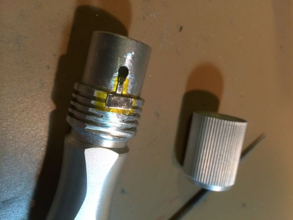
Here’s a picture of the new body with kapton tape and tin strip.  The strip links the hole on the body to the switch. The front two legs of the switch will be soldered to the wide flat area of the tin strip on top of the heatsink. The bottom 2 legs will be bent down and press-fit into small holes that will be drilled where the 2 black dots are in the center of the heatsink fins. When the pill is screwed in the switch wire will be inside the battery tube, not too far from the hole. I then use tweezers to fish it out of the hole and rest it on the tip of the tin strip, which angles down into the hole. I then use a small 6-watt battery powered soldering iron to solder the wire to the tin strip. Final step is to take a small file and quickly file down any excess solder so the join is flat and then apply a piece of Kapton tape over the hole.
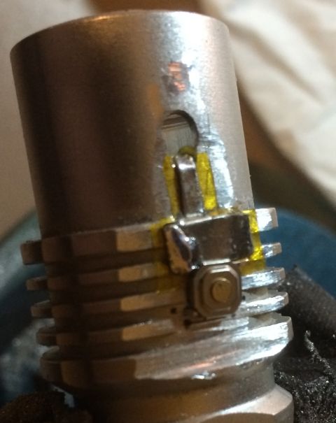
Here’s a picture with the switch soldered on:  I subsequently, inserted a piece of toothpick under the switch so it sits flat instead of being lifted up by the strip. On the first body, the switch was completely flat and used a small wire to connect it to the strip. I might go back to that method. It was a little more effort, but resulted in the switch being flatter on the light and meant slightly more pressure was required to activate the switch.
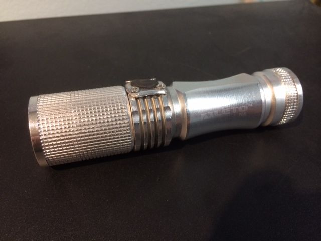
Here’s a picture of the light with the replacement body.
I used the checkering file to convert the ribbed grooves on the head into square knurling and to add a ring of square knurling at the back.
Unlike the previous body, this one retains all 5 heatsink fins. I also left the interior of the battery tube slightly longer so it can use protected cells. I made a new switch cover that is held on with 4 screws.
Wow, Firelight. This is a fricken serious mod. Really like the direction you are going with it. I wish I had to guts to attempt what you're doing here.
That is so well done! Bravo :-)
