HF might ![]() Their biggest product endorsement is “Chosen by Truckin’ Magazine,” which they use for several items.
Their biggest product endorsement is “Chosen by Truckin’ Magazine,” which they use for several items.
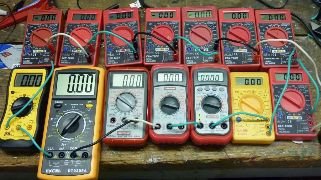
Just a warning about these free harbor freight meters. I have three of them and they all read quite differently of one another. I changed out the batteries with fresh new tested energizers and they still read incorrectly. Since I have a few calibrated fluke DMM’s, I didnt bother to look any further and threw the HF meters in the parts box. There might be a calibration pot inside to dial these in. Just dont rely on your readings until you have checked them against a known calibrated DMM and adjusted if necessary. Then recheck for accuracy every month or so. I read that a lot of cheap meters are overly sensitive to the state of the battery voltage that powers them and can also make them read incorrectly. So as the cell ages, your calibration gets thrown out the window, even after a recent calibration. :Sp Maybe thats why these are free and have been for several years.
I might dig mine out and practice my throwing sling techniques. Just hold it by the leads and give it a good throw into a concrete wall ![]()

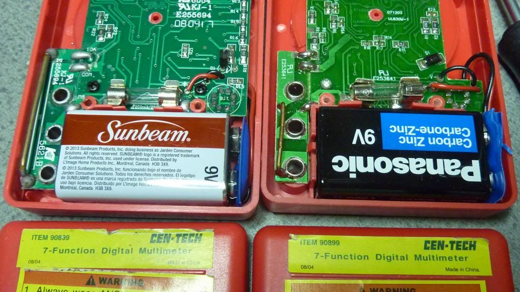
FlashPilot,at risk of being called a shill for HF, ![]() I must say that it seems HF is upping their game lately. It used to be that I could just not touch their stuff. Totally unusable, but lately their stuff has improved. Take for example this meter. It used to be the shunt resistor was longer and not mounted directly to the jacks. When passing current it had to travel through the circuit board, Now they are right next to the jacks. Here is an older #90839 and the newer #90899
I must say that it seems HF is upping their game lately. It used to be that I could just not touch their stuff. Totally unusable, but lately their stuff has improved. Take for example this meter. It used to be the shunt resistor was longer and not mounted directly to the jacks. When passing current it had to travel through the circuit board, Now they are right next to the jacks. Here is an older #90839 and the newer #90899
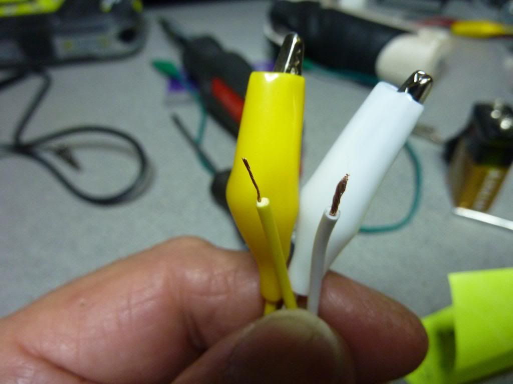
Also, I was shocked when I recently was forced to buy some more alligator clips. In the past they were terrible, totally unusable as the wire was hair thin. Compare the ones I just picked up last week with the ones from a few years ago. They package claims 18 gauge.
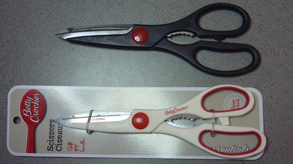
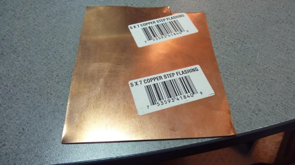
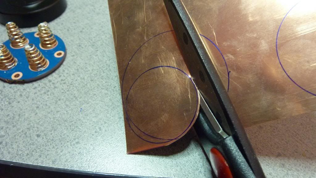
The copper step flashing I used was cut with the free HF scissors (shears). Their regular price is $1.99, on sale almost always for .99. Or you could go to Dollar Tree and get the same exact pair, in white, for $1
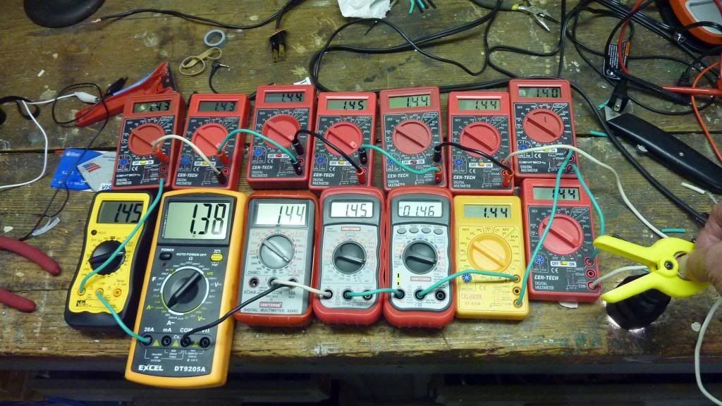
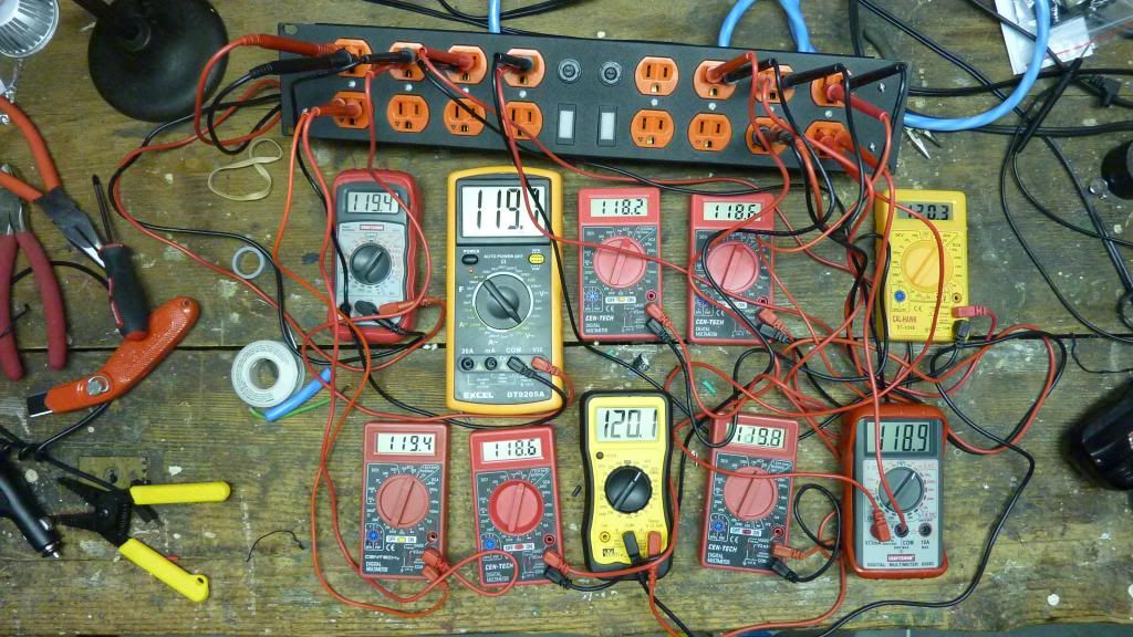
As far as these meters go, unless there is something grossly wrong with one, they pretty mcuh agree with each other.
Woops, not that one, this one.
and this
Anyway, I am not pitching HF meters in this post but an idea. That idea is central to BLF, If you don’t own it, or can’t buy it, you can make it. And have fun doing it!
Really all a meter has to do is provide you with a basis, that is, a reference.
If it is not spot on the exact value, it does not matter, what matters is that you use the same meter and record the difference before and after mods.
Most cheap meters will work quite well once you have upgraded the leads, preferably soldered them as dchomak has outlined.
As they say, “it ain’t rocket science”
Some of you guys get sooo bent on a battery charger charging .01 volt over or under like it’s the end of the world.
Then HKJ will chime in and say, BFD, it’s within acceptable spec.
This just in, the battery isn’t going to explode because your I4 charged it to 4.22 volts.
Likewise, your flashlight is going to look the same at 4.185 volts as it does at 4.20 volts, and really that battery will be down under 4.15 volts before you can type this post if your light has any kind of decent draw, so big deal.
I like specs, I just will not be lured into being, or acting like a Spec Head.
JMHO, your amperage may vary:)
Keith
Great post dchomak… you silly HF DMM mega-shill! :D. Holly smokes! Thats a lot of meters you’ve got there. :bigsmile: That pic says it all and Im impressed with the close voltage spread. Mine were off by more than .5V, as I recall. I’ll have to locate my 3 copies and see if they resemble yours. I think I got them last summer so they are less than a year old. Is there an adjustment pot anywhere on the board? Maybe hidden on the front side underneath? Hopefully one for current and another for voltage.
I got a free pair of black scissors like yours from HF instead of the free DMM last time… and I like it! Maybe I’ll keep going back with my free scissors coupon and become the HF Scissors Mega-Shill. How’d that be? :bigsmile:
Careful folks, dchomak is just trying to lull us into a false state of complacency as he silently builds his secret army of DMM's that will be used to attain complete and total World DOMINATION!
Sorry, I keep surprising myself as I continue to reach new levels of corniness.
Nice thread dcho. Very interesting and informative.
That’s right, if I can get ahold of enough meters………, well resistance will futile. ![]()
Actually there’s nothing to worry about, I’ve moved on to the free tape measures. Look for a post in the near future about my “collection” (Tongue in cheek, of course)
FlashPilot, it’s appropriate that you mentioned the Sling. A sling illustrates just what I was putting forth.
Ever hear the story of David and Goliath. Goliath was a warrior, a mercenary that fought for the enemy. He was equipped with the most modern weapons of war. He was so greatly feared that none of David’s countrymen would meet him in battle. The only one that was willing to take him on, one on one, was David. He was just a little sheep herder, not even experienced in the art of war. Nor did he have any sophisticated weapons, just a homemade sling and 5 smooth stones. And you know how that went, he got the job done, he slew Goliath.
I have a saying, “The true measure of a man is what it takes to stop him”
If it doesn’t take much to stop someone, then he’s not much of a man.
So, don’t have the tool? Don’t let that stop you!
The OP was my way of showing, members here that sometimes you may not need fancy equipment to get the job done. After all, some of us don’t have all the “toys”. Maybe they are young, or just starting out, or don’t have the money. 2 individuals that come to mind that do very well without the fancy tools is Old Lumens and ComfyChair.
And I wasn’t down playing having good tools either, that “hack” works with a Fluke also. ![]()
Lotsa luck doing that… at 0.001 ohms (even 0.01 ohms) even a tiny amount of change in wiring/component leads/soldering can be more than the resistance value you want to make. I have meters that can read well below 0.000001 ohms and getting anywhere near 0.001 ohms takes a lot of careful work with them.
That’s exactly right TP. I was able to do it by cutting a little long, making my connections, and allowing small bits of solder to wick into the wire. It wasn’t easy, but I got ’er done.
dchomak, I didnt mean to detract from your thread. I think it was an interesting post that demonstrated some good problem solving skills… and free is always better. Especially if its useful. :bigsmile:
The only reason I saved my HF DMM’s was because I might have a use for them as parts in future projects if they couldn’t easily be calibrated correctly. I picked them up thinking that a 0.1-0.2V variation would be good enough to give to others to check their cells from time to time. 0.5V or more just didnt cut it. But you know, there’s always some humor to be found while criticizing a cheap product thats completely useless. ![]() BUT, Ive been more than happy with my free HF scissors! I think there was a similar thread on BLF posted a few years back where someone used a pair of DMM’s in tandem to read higher amps but I cant find it now. Im lucky that I have access to a calibrated clamp meter if I need it.
BUT, Ive been more than happy with my free HF scissors! I think there was a similar thread on BLF posted a few years back where someone used a pair of DMM’s in tandem to read higher amps but I cant find it now. Im lucky that I have access to a calibrated clamp meter if I need it.
Ive always enjoyed the saying, “dont bring a knife to a gunfight.”
Interesting thread. I’ve always looked at meters as “black boxes” not understanding how the results were obtained. Learned a bit today, thanks. Mostly I just use mine to verify that all the 7135’s are functional or that the driver is in the ballpark but even for that I’ve had to replace the stock leads with shorter, thicker ones. This mod should get a link in one of the DIY sticky’s.
I can't believe I still having followed the advice given in the OP and made one of these external shunts yet. I generally use very short leads made each time using the emitter lead itself (use extra length for testing and then shorten for final assembly). Probably not too bad a set up, but this is much better.
I hope to build one this weekend. Thank you again for this thread. Good stuff.
I really want to make myself one of these external shunts, but I'm having trouble picturing how calibrate it. In the OP, you wrote:
From the resistance chart, it works out that 4.75 inches of 14 gauge is about .001 ohm. So I cut off a 5 inch length of wire and soldered leads a little greater that 4.75 inches apart. I calibrated it with another HF meter on the 10A scale. At first it read a little high as it was a little too long, but I reduced the resistance slightly by allowing solder to wick into the wire until is was exact.
Could you elaborate on how you did the Bold texted part above?
The easy way to calibrate is if you have a power supply with a good current limit.
Then you can measure the current, move the meter to the shunt and measure the voltage.
With tow good DMM's it is easier, because one can be used for the current and one for the voltage over the shunt.
A DMM with a very good low voltage readout is preferred for this!
Thank you HKJ. I think I'm following you. I will try that out this weekend.
My power supply is low end, but I have hooked up DMM's directly to it and have had matching readings on current (within a few milliamps). I don't have a good low voltage DMM, but the rest of what you say should get me most of the way there. Basically, I think you're telling me I should be able to get separate readings from 3 different units (Power Supply Meters current and voltage, DMM current, DMM voltage) to get some comfort with the external shunt.
Yes, when you know the current in the shunt you can use the DMM to verify the reading.
With a 10mOhm shunt you need a meter that is fairly good at low voltages..
I do most of my chargers test with a 10mOhm shunt and a 6½ digit bench DMM, but because I do not maintain calibration factors for the shunts (or calibrate them) I have a few percent tolerance on the current measurement. If I had done some calibration I could get below 0.5%.
BTW, I did not make a .001 ohm resistor, what I did was take a piece of wire and solder connections to it, that after fine tuning, those 2 connections became exactly (well not exactly) .001 ohms apart. There is a subtle difference between the 2, but that difference makes this possible.
I am assuming you know how to make the shunt, what you are asking is how to calibrate it, right?
What I did is put the shunt in series with a HF meter while passing current through both. Then fine tuned the resistance of the shunt so that the voltage read across it corresponded to the current given by the HF meter on the 10A scale. Of course it would only be as accurate as the HF meter. If you have a known current source, there is an easier and better way.
The key to this whole idea is that in constructing the shunt, the first step is soldering test leads to the shunt, before any calibration. This is what makes all this possible with cheap meters. This eliminates contact connection and exact location issues with the shunt resistor and BTW this is a 1 milli ohm resistor, for the lowest possible voltage drop while measuring current.
Once the initial connections are soldered in place and a dedicated meter is chosen (HF meters are cheap or free) The rest of it is fine tuning the resistance between the connection points.
I don’t see why a very good low voltage readout meter is necessary as during the tuning (calibration) process the meter - shunt resistor combo will be calibrated together. If the meter was off in the first place it wouldn’t even matter. Calibrate the combo for the known current flowing through the shunt. Now if a cheap meter is sensitive to a weak battery, that would be another matter.
If the shunt was a separate piece of equipment, then that would be a different matter and every piece of equipment would have to be of high quality.
Because I prefer a resolution in mA, not in Ampere. At 1mOhm 1mV is 1A, i.e. I would want a resolution of 10uV or better (10uV means 10mA in resolution) for most of my measurement.
If I am going to measure above 10A I would probably use a current clamp. If the current was supplied by my (now dead) power supply I could get the value directly from it and not worry about clamp or small value resistor.
Thank you both for your advice. This is on my list of things to try to get done today.
I hope you all don't mind another question. I would like to make one of these shunts for testing current flowing to the emitter. So I will need some extra length to string it from the emitter base to the driver. So the shunt will have the leads for reading voltage somewhere along the shunt wire well away from the ends. When I calibrate, I will be sending x amps through the whole length via the bench top power supply. Do I need to compensate for the extra length of shunt wire outside the voltage meter lead attachment points? I think the answer is no, I don't need to compensate for that.
Another related question. As I use this external shunt, I will periodically need to trim off some of the ends as they will deteriorate from repeated soldering. Will the trimmings require recalibration? I think the answer is no.
Actually, even bigger related question. Then I am calibrating the shunt, I will have like 3/8" or so of each end clamped in the bench top power supply jacks. But when I use the shunt, the ends of the shunt wire will be soldered to a driver and emitter base with no clamps. Do need to alter how I attach the shunt wire to the bench top power supply to make it more similar to how it will be used for measuring current to the emitter? Again, I think the answer is no.
Really, all the 3 questions above are the same question. I think the important part is area between and including where the voltage measurement leads attach to the shunt wire.
Now a somewhat less related question. Why are we not concerned about voltage drop along the leads that go to the DMM that will be measuring the voltage drop along the shunt?