Thank you very much, wight, that clears matters up for me.
I fiddled around with pipe tube parts in the past, like adding several concentrical rings to a 17mm driver. It works, it’s budget, but your approach is way better.
I downloaded Eagle in the meantime, but it seems you have a different file format. Is there a software (preferably free) to make or alter these PCB designs? You just opened a can of worms here. I can well use the 26mm variante, but I could need 23.7mm (Maxtoch HI6X-17) and 22mm (Ultrafire F10). Oh this might come in handy…
Edit:
This had been my approach till now, yours is slightly more sophisticated…
PCB manufacturing uses a format called Gerber. That’s what those files are. I did use Eagle to produce those layouts, the appropriate files for Eagle are .brd files: http://photo.jesusthepirate.com/blf/26mm_contact_board/
Note that v4 are what I shared on Oshpark. v6 uses an unsupported drill size to create a large via (plated hole) instead of a routed hole. v6 may or may not actually work The PCB house used by Oshpark specifically does not support plated slots on these boards, but who knows if you could get away with specifying a giant drill hit (16-18mm) and via.
Wow, thx for the link to the brd-files, I was able to open these in Eagle (v6, though).
The program is, well, err, mildly intuitive… but I was already able to move some vias.
I found Mattaus Eagle Tutorial, that’s exactly what I need right now.
I’m thinking of placing the vias closer to the center and all copper visible, so I could grind down any 26mm board to a needed size. Still easier than my last approach or having 18 and a half different board sizes to design.
Your board looks slightly different in Eagle than at Oshpark. So you designed them in Eagle, how did you upload them, as .brd or somehow pre-converted?
At Oshpark other boards are sometimes .zip (Gerber?) but also sometimes .brd, that still puzzles me.
To make gerber files out of eagle brd files you use Eagle’s CAM processor. Oshpark has an Eagle CAM processor built into their site, so it is possible to upload .brd files directly. When sending to other places you typically must provide gerber files. Doing the CAM processing yourself helps make sure that the Eagle file is interpreted the way you want.
I did intend to link you to Mattaus’s Eagle tutorial, but I forgot. Good thing you found it yourself.
Eagle’s presentation of boards is different from Oshpark’s. For one thing, Eagle shows you the mirror view of the bottom side, Oshpark does not. Not such a big deal here of course since the whole board is symmetrical
Leaving off the solder mask is fine. I actually took it off myself and then put it back for the reason I mentioned above - to clean up the soldering process a bit. Note that you can move items parametrically by right clicking and editing the Properties of any given item. That will allow you to directly set the X and Y coordinates for precision placement.
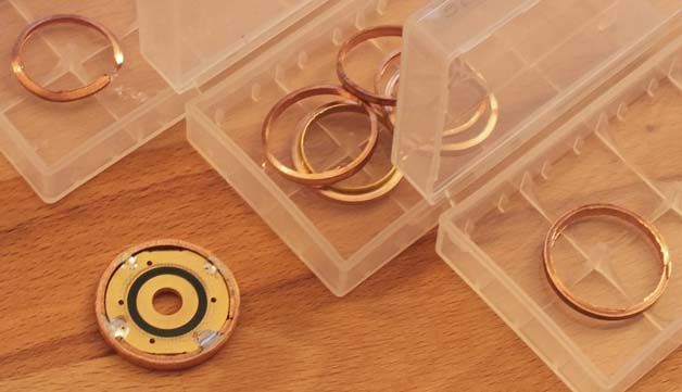
I was thinking of doing breakaway tabs for a more flexible contact board, but never made it that far. Instead I made this 22mm contact board.
16mm tabs for 17mm driver or file to match outer radius to get a 18mm circle for a 20mm driver.
EDIT: those are the tightest turns you can make at Oshpark. They use a 0.1in endmill for the cutting.
It depends on the CAM processor, if someone uploads a .brd file OSHPark renders the file then generates their own gerber files for the manufacturer, pre-generating and zipping for them just skips the step of them having to convert .brd to the CAM files (gerber) files
Mattaus’s CAM processor is so easy to use…just design the board, open the cam processor, load the board, hit the generate button, zip up all the *.CAPLETTERFILES in the directory and viola…instant zip file ready for OSHPark (I added a top and bottom paste layer to his processor so it will have the cream layers to work in OSHStencils)
Err, the more I think about it the more I wonder whether that latest board I posted would be sturdy with a 17mm driver installed. The contact patch should be approximately 8 linear mm (2mm long across each tab) by 0.5mm deep. So ideally you are getting… 4 square mm of soldered contact area. As long as the traces on the 17mm PCB don’t lift/tear I guess it’s OK.
Maybe if you had extra tabs at 12 and 6 oclock, more work to fit…but would really increase the area for soldering to the ground ring, much more rigidity and strenght
Wow, I’m still trying to find the bottom layer in Eagle, and you bring up truly fancy stuff here.
If you could
a) extend the 4 inner lips just so far, that a 17mm driver can be put on top instead of being soldered planar
- then you have the option to file it down to 17mm if you want it planar, but you needn’t. I second the idea for a 5th and 6th lip.
b) extend the whole piece to 26mm while keeping the vias exactly there.
then you can grind it down to any diameter between 26 and about 22.
That would be a very variable board for 17 to 20mm driver and 22 to 26mm outer diameter. PCB can be shortened with a dremel and a sanding piece in no time.
In response to your earlier comment - yeah, Eagle is the the devil. It’s super-not-intuitive. Somehow I’ve started to get used to it. I have also messed with Kicad some, it was different but not better.
I haven’t shared it…if you would like it shared let me know
Very cool having a modular type contact ring that with a little grinding can make fit multiple pills
Here is Mattaus’s CAM processor that I added the top and bottom cream layer…just put in the cam directory of Eagle install, when you get your board built save it, open the CAM processor, open the board, generate, zip up the all caps files and upload to OSHPark, you can also upload to OSHStencils and select the correct cream layer for a stencil