Yea, I think they look off too. 0805 should have a pad separation around 0.7mm. Oshpark renders boards using tStop for the copper areas instead of Top for some reason. Makes all pads look 3mil larger in the renders.
Are you using the oshpark DRC? The default eagle DRC has 4mil mask instead of 3.
I don’t know, even if its the eagle default 4mil, pads look off. Course I didn’t sleep last night so my eyes might be off.
Oh so this isn’t a single emitter driver but a multiple in series driver…k gotcha
Cool project. Thanks for starting and sharing this.
I didn’t realize that I could adjust that - I see it now. Thanks. I had it set to the default, 4mil. I’m using the Eagle R0805 package for the divider resistors and C0805 for the caps.
WarHawk-AVG, please read the thread. It’s a buck driver and will go at least low enough for a single white emitter. Results are posted in the short thread I linked. The driver will not operate on a single lithium ion cell. The links in the OP were meant to answer this question.
Thanks, let’s hope we get something useful out of this thing. I’m feeling pretty good based on the lineage (all the other successful drivers based on this controller). The only thing that I’m concerned about is how big an efficiency hit we take from eliminating the weird dual-FET setup I mention in the OP. It’s not a synchronous buck configuration, so I really don’t understand what those other designs are doing with the second FET.
Yup…I shoulda read…thanks wight
I realize that I post a lot of links. ![]()
While searching for boards to rob components from in order to populate this driver, I came across this:
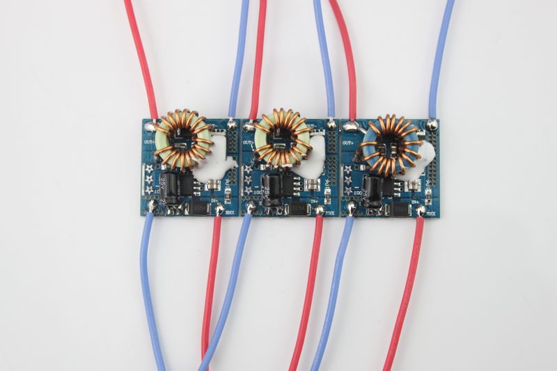
http://item.taobao.com/item.htm?id=17981669490
At ~$2.50/each in China I figure that’s not much better than the new-version DRY driver. Has anyone seen these drivers around on AliExpress or eBay for a better shipped price? I see them on eBay for crazy prices (>$10!!), but no decent prices.
I’ve just taken a closer look. I’m seeing about a 0.16in / 0.4064mm spacing. Are you guys using the stock Eagle libraries or something else? Thanks.
EDIT:
Well, I made some mild placement adjustments, cleaned some things up, and fixed a couple of DRC issues. v014 is ordered for testing. I don’t have a lot of parts to test with, so let’s hope it doesn’t fry stuff.
I have quite a few custom .lbr
I also use 0603 pads, my 0805 components fit just fine on the pads when I use hot air to reflow the components
Might just give you a bit more space on your placement
Custom Eagle parts makes sense. I’ll have to take a look at these PCBs when they arrive (since I know exactly what Eagle parts I used) and compare with real life 0805 components.
While looking at other drivers I recently realized that there’s no reason for me to fret over the need for a big inductor. I’ve been looking for wrapped toroids like we find on the DRY driver and original SRK driver, but I wasn’t able to figure out where to shop parametrically to find high-current toroids at the desired inductance. Turns out there’s no reason not to plop a (phsyically smaller!) SMD inductor right on top of all the other parts. It’s big enough to easily hookup with an air-wire.
This solves half of the crisis I was running into… the parts on the new-version DRY driver are probably spec’ed for 3-5A, it’s hard to say. zeremefico showed the driver running at 7A, but he did not discuss heat. I assume that at that current the diode and inductor are putting off some heat due to being under-spec’ed. I know people are going to want more current. A bigger diode is possible with a redesign and easy to source. We’ve already got the FET bit mostly figured out, that’s old news. So the missing link was the inductor. ![]()
Big inductors still cost a few bucks and the corners start to poke out past 16mm or so, but I think this is doable.
Just realized that I’ve been developing this driver on a 16mm PCB, not 17mm.
FWIW the lfpak56 is about half the size of the larger fets and is rated for 100A if you find board space tight. There’s an even smaller “33” rated for 60A. The design is only a few years old so it might not go out of production soon like the Vishay did.
Thanks RBD. I’m going to look into that package, space is tight if I try to put an SMD inductor on the board.
The particular DPAK Vishay product we were buying on eBay was no doubt out of production long before we started buying it. Powerful DPAK/TO252 FETs will probably be produced until after we are dead. There should really be no fear of the supply of DPAK FETs drying up.
Well, thanks again RBD. That was a great suggestion, and together with making my work area an actual 17mm circle instead of 16mm (!), that freed up a lot of space. The pin configuration is also different, in a good way. I’ve done a total rework on the board.


- SMD inductor. There is space for approximately an 8x8mm inductor. I will rework the pads to better accommodate various landing patterns.
- ~1.1mm uncovered via to add a big wire-wound toroid inductor instead of the SMD one. This is just an option in case that makes sense for a build.
- Large +/- LED pads on more or less opposite sides of the board.
- Swapped diode to top of the board. Lots of space for the diode. You should be able to fit various ~5A diodes on those pads
- Moved MCU to the bottom
- LFPAK56 / SOT-669 / Power-SO8 style FET - there should be many options for this
- Three 1206 sized sense resistors, still on bottom.
- The bottom now has a smaller component height. You should be able to use a standard Nanjg 105c spring (5mm x whatever) or a standard 5x2mm brass peg. I’ve removed the wings from the 5mm BAT+ pad though, so in order to install it you need to put it on before the sense resistors. There is a large copper pour between them, just heat the pad using the sense resistor pads.
- I kept the offtime cap, but I also brought out PB2 on top of the board. It’s available with a covered trace between inductor and FET - just scrape off the resist. This can be used for an e-switch, but like I said before this driver will have a really high parasitic drain and is a bad choice for an e-switch. I’ll probably remove most or all of this trace when I rework the inductor pad area anyway.


So here are the gotchas:
- While the new-version DRY board has been run up to >7Amps by zeremefico, the diode will probably generate a lot of heat and could fail. AFAIK diodes in this style of package are only available up to around 5A, other packages such as DPAK are used for larger diodes. Therefore the current revision of this board is intended for ~5A or less operation.
- I don’t have a complete grasp on inductor selection. The QX5241 does not have a fixed operating freq, the freq varies due to various factors: Vin to Vout ratio, drive current, inductance, maybe other stuff. The maximum the QX5241 can handle is 2Mhz. With the space limitations of a 17mm board, I think the highest inductance we can hope to achieve is 6.2uH with what I assume is a relatively expensive Coilcraft inductor. For cheap options we are limited to 4.7uH or less. Those inductors are readily available in the $0.65 to $2.00 USD range in values that can handle >5A without burning a lot off as heat.
Not a gotcha, but the overall size of v020 is similar to that of a Nanjg 105c - this board is about 1.0-1.5mm taller depending on inductor selection.
On the FET’s that I have the drain is the big tab and bottom plate, the gate is the single pin you have as the gate, and the source(ground) is what you have connected to the diode.
Well that’s bad. Let me go back and look.
I had the part right, it’s as you say. I got those backwards when I hooked it up in the schematic. Grr.
Better now than later. ![]()
Absolutely. It’s actually no big deal, there’s so little going on on the top, and so much space, that it’s just a non issue. I’m wasting a little time making things decent, but I’m not going for really nice at this point. I’ll post a new version in a few.