Does that reduce maximum output? He's mentioned a mod that would allow much lower lows.
Reduction in max output depends on which inductor you pick, both the DC current rating and the inductance rating. Comparing ~15A-rated 0.58uH inductor to a ~15A-rated 1.2Uh inductor, the 0.56 will have less damping effect on the lowest modes but also the least impact on the straight DC 100% mode. The 1.2uH will give a lower low but with slightly less output on 100% mode. But it's in the range of a few milliohms. With a ~4mOhm Rds(on) FET you can afford to sacrifice a little at the top end and not see a big hit in total output.
I don’t know if you know just how relieved to have this finally working! I was about to completely give up on my modding skills and be so discouraged that I stop again for a while. I can’t WAIT to see some impressive results for once!
On a side note, I tried modding my TR-S700 with a couple of the FETs Richard sells (it's a FET driver to start with) hoping they would allow more current to the emitters but I only gained just under 200 lumens. Still only 3745 OTF with 7 LEDs and 3*26650. Not at all what I was hoping to see. :(
http://www.digikey.com/product-detail/en/ETQ-P6F0R6BFA/PCD1393CT-ND/308387 or http://www.digikey.com/product-detail/en/ETQ-P6F1R2HFA/PCD1307CT-ND/281422, I found both on ebay for much cheaper. Anything with similar specs will do the same job, and we tried to lay out the inductor pads on the board to be compatible with just about anything in that size range regardless of manufacturer. Lots of stuff out there that will work.
This is the diode needed at D2 if using the inductor - http://www.digikey.com/product-detail/en/MBRS540T3G/MBRS540T3GOSCT-ND/918011 - or, again, something of similar specs. It just needs to be able to shunt the leftovers stored in the inductor when the FET is turned off via PWM in the less-than-100% modes.
Multi-cell buck or boost drivers don't rely on the ultra-low resistance FETs anything like a single cell direct drive driver does. Multi-cell stuff has enough voltage overhead that a high resistance FET is easily compensated for.
Same voltage as an SRK as they are parallel cells.
Thanks. That's what I needed to know to build one of my SRK's. I had been wondering why the C+ pad was so big. Now it makes sense. It needs to be able to handle different things. I'll place an order on Digikey tonight.
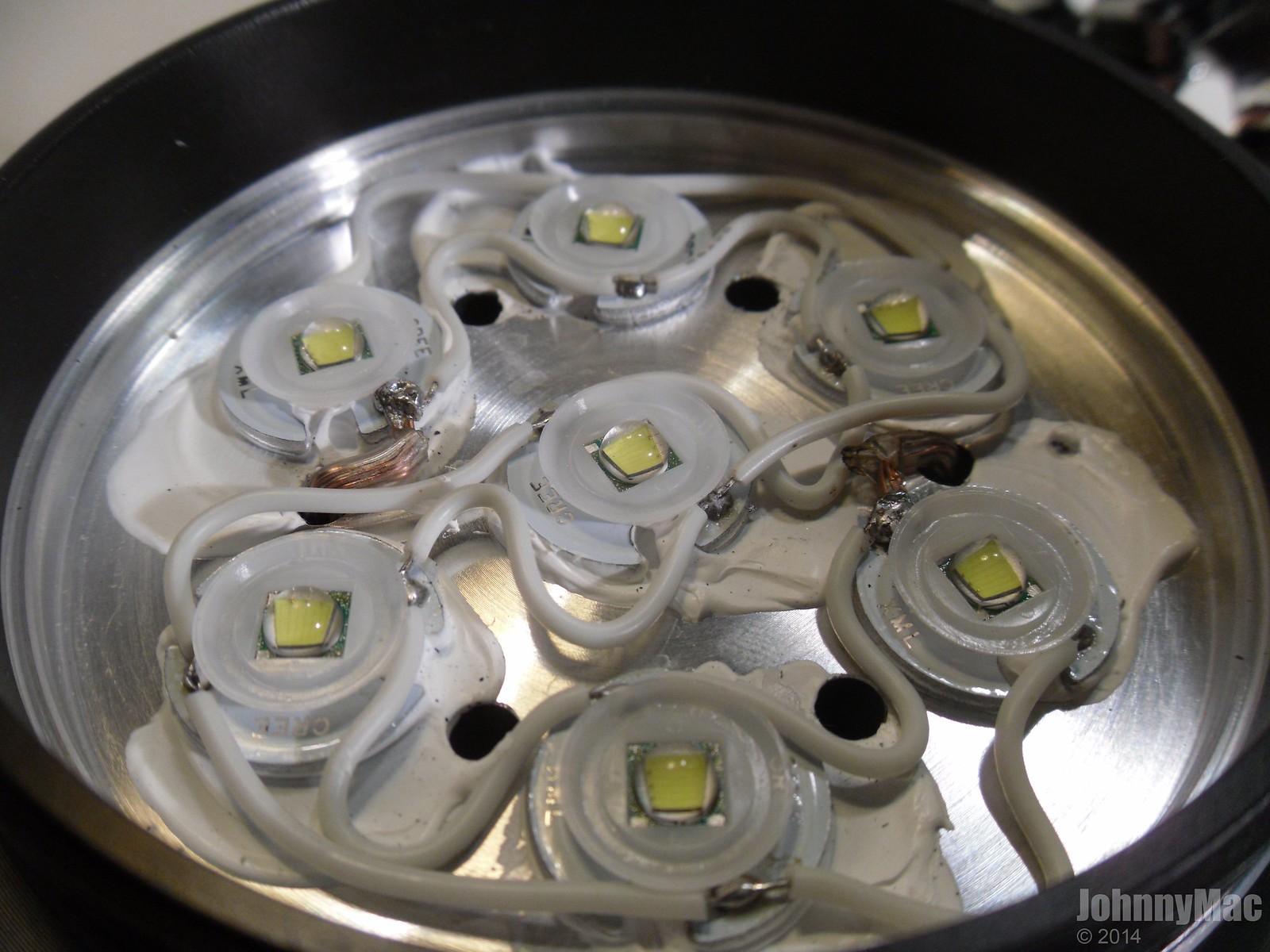
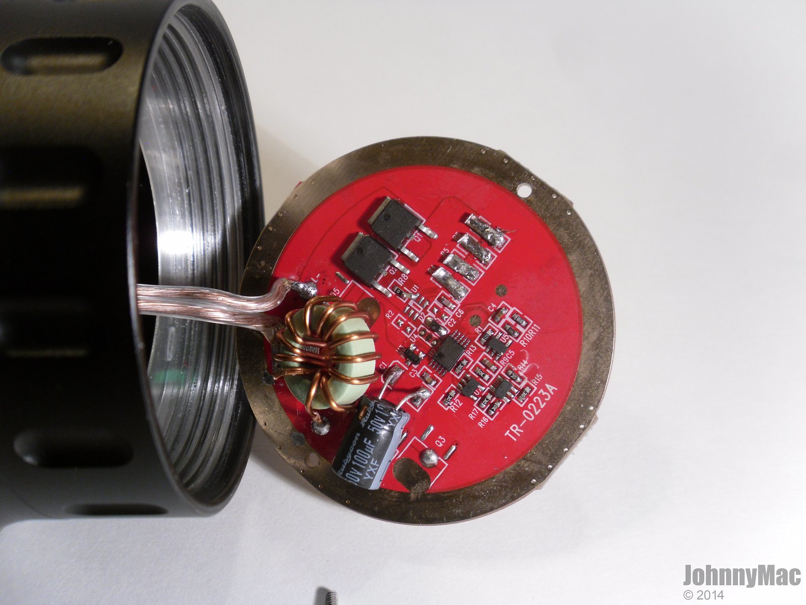
How are the LEDs wired? Got any pics of the driver innards?
The emitters are wired in parallel. Here is a pic of the emitters on the sink:
Here is the driver. At the time of the pic I'd already upgraded the LED wiring and bridged the sense resistor pads but IIRC they were always empty but don't hold me to that. Since the pic I've replaced the two FETS with two 70N02 FETS. Marginal gains with either mod.
Thanks Johnny, the link is in.
Yup, just saw that in the picture…no inductor, jumper the pads
Ebay seller 'rfextra' has lots of goodies, if you don't need a large enough quantity to get the price breaks from Digikey or Mouser. The big diodes are fairly cheap at retail in small numbers, the inductors are not.
IRF 60V/3A Schottky Rectifier 30BQ060TR,SMC,Qty.50 - $6.99
http://www.ebay.com/itm/150201700078
Coilcraft 1.2uH 12.3A Power Inductor MLC1260-122MLC, RoHS, Qty.10pcs - $6.99
http://www.ebay.com/itm/181286346884
Coilcraft 0.8uH 12.4A Power Inductor MLC1250-801MLC, Qty. 10pcs - $6.99
http://www.ebay.com/itm/160974587402
Coilcraft 0.68uH 12A Power Inductor DO3316P-681HC, Qty. 10pcs - $5.99
http://www.ebay.com/itm/160664715456
Panasonic 1.2uH 14.2A Power Inductor ETQP6F1R2HFA. Qty. 5pcs - $4.99
http://www.ebay.com/itm/400433611169
Panasonic 0.58uH 19A Power Inductor ETQP6F0R6BFA, RoHS. Qty. 5pcs - $4.99
http://www.ebay.com/itm/400257620168
OK. I'm about to flip my shit! Soldered the pads and still nothing. Examined all the soldering points on the chips and they appear to be OK. Checked switch continuity yet again and it beeps when I press the button. What the hell is going on here??? Apply power directly to the LED pads and it lights up. Has anyone ever got a defective board from RMM? I'm at my wits end with this issue. 
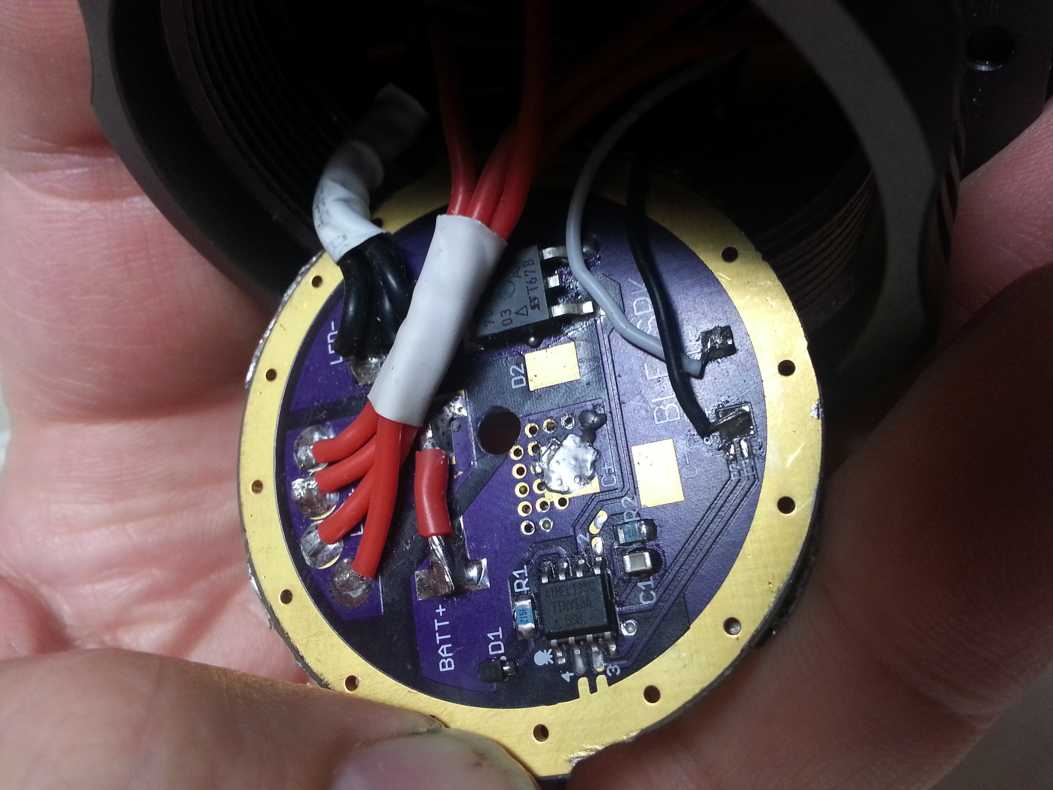
I've also applied power directly to the cell side contacts to rule out the battery tube to head contact issues. Nothing.
Have you checked for ground at MCU pin #2 while the button is pressed, and no ground when it's not pressed?
Did you build this with a parts kit or was it pre-assembled?
Yes I checked and the pin 2 pad is bridged to the switch pad. Is that what you mean?
I bought this preassembled from Richard
He took me to connect to p3 instead of p2!? Maybe you can give that a try.. take away the connection to p2 and reconnect to p3?
Did you make that hole in the middle? Maybe something gets shorted there?
Gonna do that right now. Thanks, Chibi!
Have you tried touching battery positive to the bottom trace and battery negative to the ground ring?
As many have said the OSHPark boards are thinner than stock SRK boards, you might not be getting good continuity between the battery tube on the bottom of the head to the ground ring on the bottom of the board
Appying power directly to the LED pads bypasses everything in the system…you need to feed power thru the board to check full functionality
This is why people are putting solder blobs on the top of the ground ring to thicken the board so it will contact the unanodized top of the screw in battery compartment for continuity
W00T! That did it, Chibi!!! The switch needed to be bridged to P3, not P2. Only one supremely disappointing thing. I gained a whole whopping 300 lumens. How the hell can this driver give 5000 lumens at startup on an SRK if it only makes 3000 in a terminator?