Same voltage as an SRK as they are parallel cells.
Thanks. That's what I needed to know to build one of my SRK's. I had been wondering why the C+ pad was so big. Now it makes sense. It needs to be able to handle different things. I'll place an order on Digikey tonight.
How are the LEDs wired? Got any pics of the driver innards?
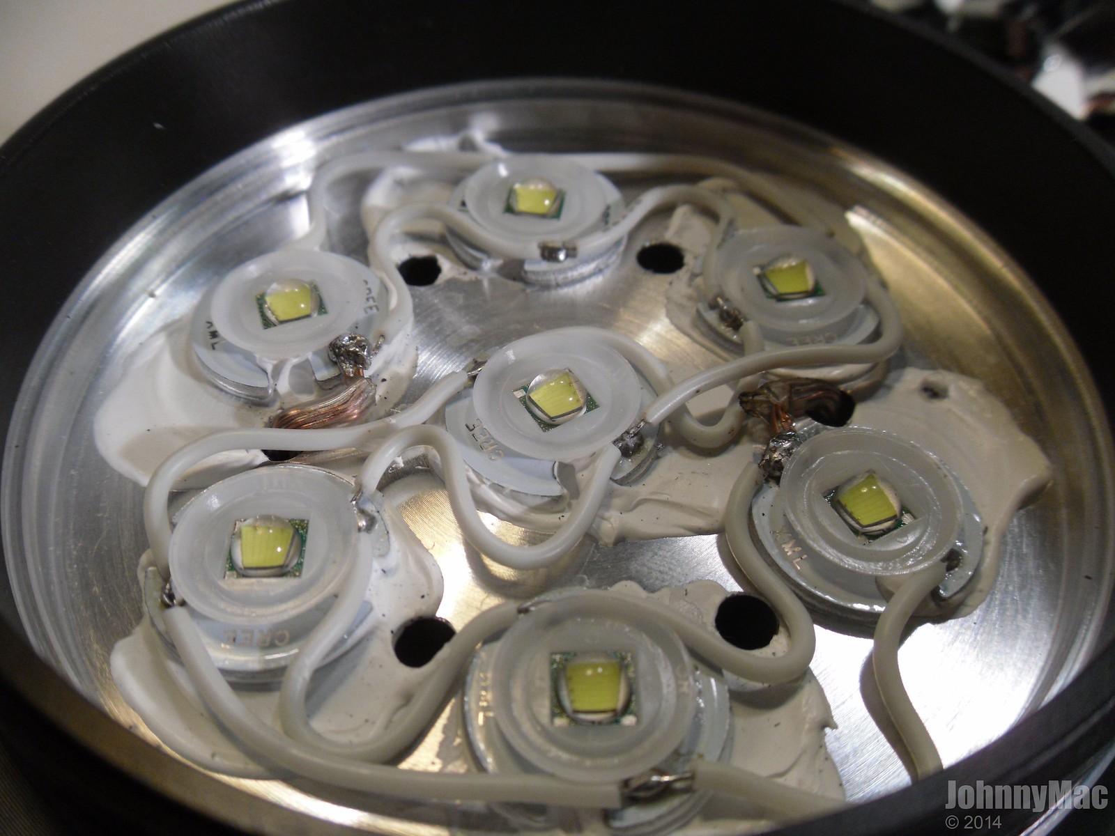
The emitters are wired in parallel. Here is a pic of the emitters on the sink:
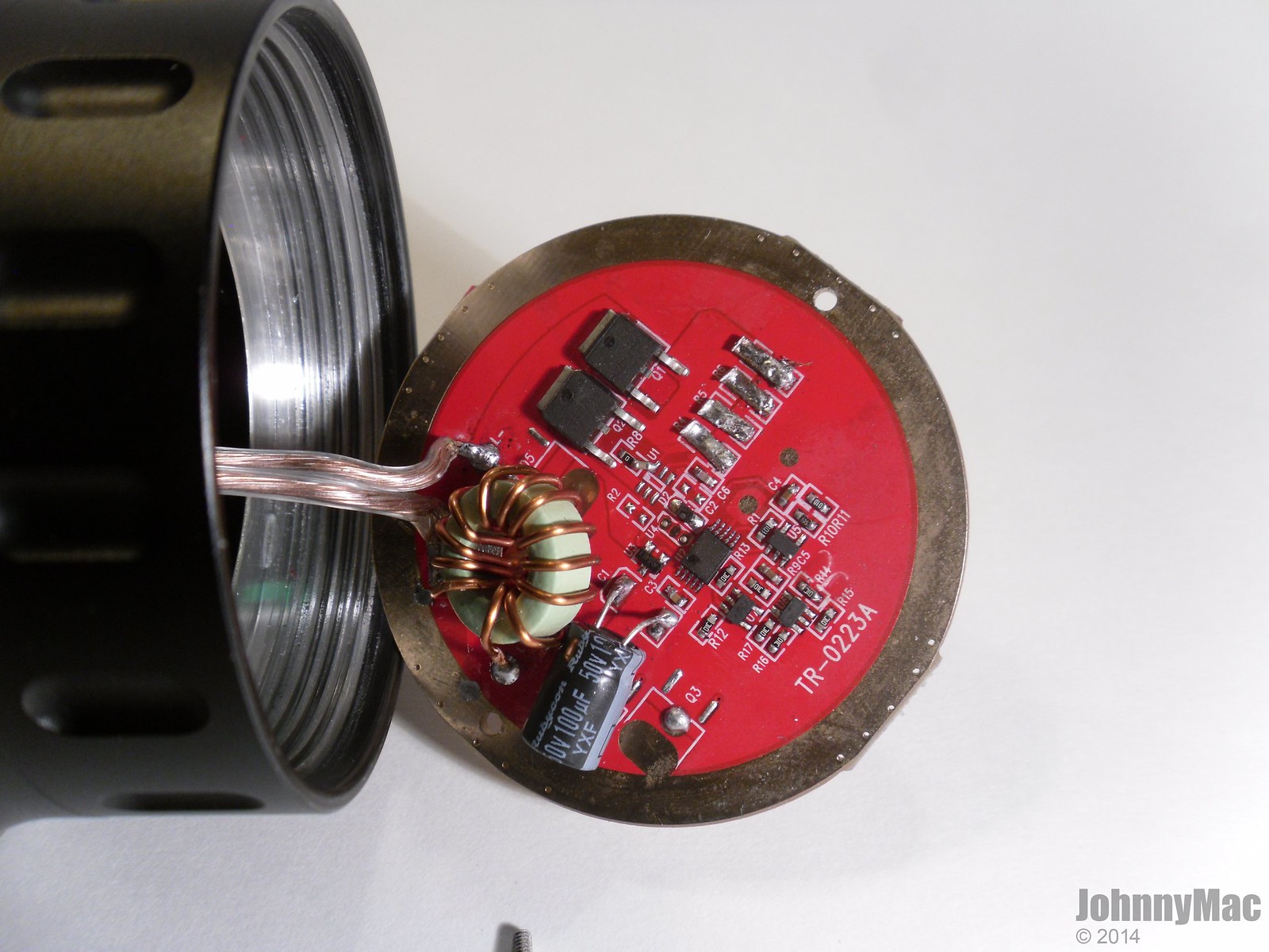
Here is the driver. At the time of the pic I'd already upgraded the LED wiring and bridged the sense resistor pads but IIRC they were always empty but don't hold me to that. Since the pic I've replaced the two FETS with two 70N02 FETS. Marginal gains with either mod.
Thanks Johnny, the link is in.
Yup, just saw that in the picture…no inductor, jumper the pads
Ebay seller 'rfextra' has lots of goodies, if you don't need a large enough quantity to get the price breaks from Digikey or Mouser. The big diodes are fairly cheap at retail in small numbers, the inductors are not.
IRF 60V/3A Schottky Rectifier 30BQ060TR,SMC,Qty.50 - $6.99
http://www.ebay.com/itm/150201700078
Coilcraft 1.2uH 12.3A Power Inductor MLC1260-122MLC, RoHS, Qty.10pcs - $6.99
http://www.ebay.com/itm/181286346884
Coilcraft 0.8uH 12.4A Power Inductor MLC1250-801MLC, Qty. 10pcs - $6.99
http://www.ebay.com/itm/160974587402
Coilcraft 0.68uH 12A Power Inductor DO3316P-681HC, Qty. 10pcs - $5.99
http://www.ebay.com/itm/160664715456
Panasonic 1.2uH 14.2A Power Inductor ETQP6F1R2HFA. Qty. 5pcs - $4.99
http://www.ebay.com/itm/400433611169
Panasonic 0.58uH 19A Power Inductor ETQP6F0R6BFA, RoHS. Qty. 5pcs - $4.99
http://www.ebay.com/itm/400257620168
OK. I'm about to flip my shit! Soldered the pads and still nothing. Examined all the soldering points on the chips and they appear to be OK. Checked switch continuity yet again and it beeps when I press the button. What the hell is going on here??? Apply power directly to the LED pads and it lights up. Has anyone ever got a defective board from RMM? I'm at my wits end with this issue. 
I've also applied power directly to the cell side contacts to rule out the battery tube to head contact issues. Nothing.
Have you checked for ground at MCU pin #2 while the button is pressed, and no ground when it's not pressed?
Did you build this with a parts kit or was it pre-assembled?
Yes I checked and the pin 2 pad is bridged to the switch pad. Is that what you mean?
I bought this preassembled from Richard
He took me to connect to p3 instead of p2!? Maybe you can give that a try.. take away the connection to p2 and reconnect to p3?
Did you make that hole in the middle? Maybe something gets shorted there?
Gonna do that right now. Thanks, Chibi!
Have you tried touching battery positive to the bottom trace and battery negative to the ground ring?
As many have said the OSHPark boards are thinner than stock SRK boards, you might not be getting good continuity between the battery tube on the bottom of the head to the ground ring on the bottom of the board
Appying power directly to the LED pads bypasses everything in the system…you need to feed power thru the board to check full functionality
This is why people are putting solder blobs on the top of the ground ring to thicken the board so it will contact the unanodized top of the screw in battery compartment for continuity
W00T! That did it, Chibi!!! The switch needed to be bridged to P3, not P2. Only one supremely disappointing thing. I gained a whole whopping 300 lumens. How the hell can this driver give 5000 lumens at startup on an SRK if it only makes 3000 in a terminator?
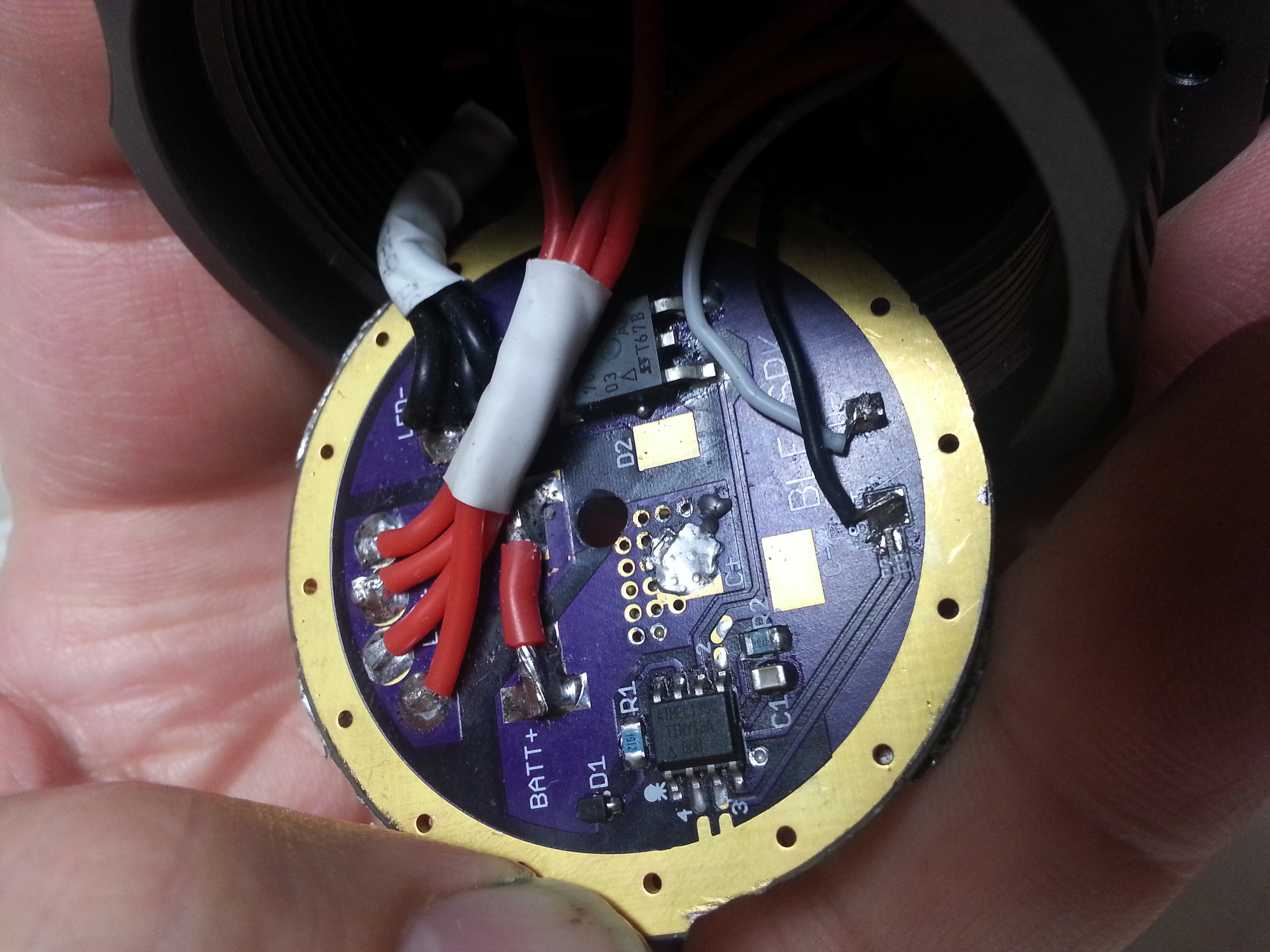
There's some confusion of the numbering. 'P2'/'P3' down at the SW+ pad refers to which pin on the MCU it goes to. But up at the MCU, there are pins marked '2'/'3'/'4', which correspond to the numbering of the stars on the old Nanjg boards this part of the circuit was copied from.

My red numbers...
1: Why is the end of that pin black, and not shiny solder like all the others? That pin should have battery voltage at all times with power applied.
2: What are the markings on the small diode?
3: Pin #4 must have ground at all times, and the hole being filled with solder bothers me a little bit. What's on the other side? Make sure that pin has continuity with the ground ring.
The big hole in the middle bothers me a little bit too... are you ABSOLUTELY SURE that hole is clean, that there's no little bits of metal hanging around going somewhere they shouldn't? Are you testing out of the light, or assembled with that screw in place? What does it thread into in the head?
Better FET, do you use the same wires?
Glad you got it working
In JonnyC's original source code it says:
#define SWITCH_PIN PB3 // what pin the switch is connected to, which is Star 4
...and PB3 is pin #2 on the MCU.

If it only works with the switch grounding pin#3, and not pin#2, then somebody altered the pin assignments in the firmware.
What cells are you using? It will only do the big numbers with something like INR 20R/25R or Sony VTC4/5s. On tame ICR cells it isn't going to pull more than 10-11 amps.
Well, good news and bad news. That 3000 lumens was on 3 LEDs. Apparently one of the defined emitters was OK for 2.8 amps but it blew with the new driver. The bad news is I don't have any more XM-L2 U2 emitters to reflow and dedome. I need to order some from Illumn. At least i know it works now and will know what to do in the future with my other SRK driver. :D
Comfy, I will break out the good camera and get a macro of the second driver for you. Hopefully it will show what you wanted to see.