doesn´t work with an attiny13 
hi crux,
i got a little help from tido and the first driver is running. first pb0 will be active for the red led. then you can switch the programmed mode output on pb1. now i understand a little more about the µc.
markus
I hesitate to ask for help because C-programing is out of my element (I'm hardware), and I don't want to waste anyone else's time.
I figured that if I could compile the stock driver.c code to a working .hex file then I would try tweaking the code to my needs. But alas,when I build it I got errors saying mode_sos and mode_softbeacon are "undeclared here (not in a function)". So I changed the source to look like this:
//#define NOMEMORY // #define to disable mode memory
#define FUNC_STROBE // #define to compile in strobe mode
#define FUNC_SOS // #define to compile in SOS signal this line was commented out
#define FUNC_SOFTBEACON // #define to compile in softbeacon mode I added this line
//#define FUNC_ALPINE // #define to compile in alpine distress signal
Now it compiles, but it's too big, 1088 bytes (with optimization -Os)!
Device: attiny13a
Program: 1088 bytes (106.2% Full)
(.text + .data + .bootloader)
Data: 36 bytes (56.2% Full)
(.data + .bss + .noinit)
EEPROM: 64 bytes (100.0% Full)
(.eeprom)
I suspect I don't have something configured just right, but what - there so many things to learn (and so little time)...
BTW I'm using AVR Studio 5.
Any or all help is appreciated.
-Crux
There are a few places in the code you will have to change if you are adding a new function. Let's assume that FUNC_FADE did not exist before and we are adding it. First, you will probably want to define a new mode line. This is a handy short cut and makes reading the EEPROM set up easier. It looks like this:
#ifdef FUNC_FADE
#define MODE_FADE   0x04, 0xFF, 0x01, 0x01  // fade in/out. Just a gimmick
#endif
MODE_FADE is the name for the mode, the first number is the offset into the function-array (more on this later) and the three remaining numbers are the three parameters the function may use.
Next you set up the EEPROM. This is where you add the mode line:
const uint8_t EEMEM eeprom[64] =
{   0x00, 0xFF, 0xFF, 0x00,
    0x00, 0x00, 0x00, 0x00,
    0x00, 0x00, 0x00,
    // initial mode programming, indices to mode lines in the following array
    0x03, 0x06, 0x08, 0x00, 0x00,
    // mode configuration starts here. Format is:
    // offset in mode_func_arr, func data1, func data2, func data3
    MODE_LVL001,    // 0x00
    MODE_LVL002,    // 0x01
    MODE_LVL004,    // 0x02
    MODE_LVL008,    // 0x03
    MODE_LVL016,    // 0x04
    MODE_LVL032,    // 0x05
    MODE_LVL064,    // 0x06
    MODE_LVL128,    // 0x07
    MODE_LVL255,    // 0x08
    MODE_STROBE,    // 0x09
    MODE_POLICE,    // 0x0A
    MODE_FADE       // 0x0B <= new mode line replaces another
};
By placing the #define for the mode lines inside the #ifdef FUNC_<name> earlier, this will result in a compile time error if the EEPROM config contains a mode which has not been compiled into the binary. This is a Good Thing™. You got the compiler error because you disabled the code for the SOS-function, but your EEPROM set up still contained MODE_SOS.
Next you will have to give a forward declaration for the new mode function:
#ifdef FUNC_FADE
void fade(uint8_t offset);
#endif
This is necessary to add the function pointer to the function pointer array:
mode_func mode_func_arr[] =
{
        &const_level
#ifdef FUNC_STROBE
        , &strobe
#else
        , &nullmode
#endif
#ifdef FUNC_SOS
        , &sos
#else
        , &nullmode
#endif
#ifdef FUNC_ALPINE
        , &alpine
#else
        , &nullmode
#endif
#ifdef FUNC_FADE
        , &fade
#else
        , &nullmode
#endif
};
Why this #ifdef FUNC_<name>, &func #else , &nullmode #endif construct? This makes sure that the functions keep their place in the array by replacing functions that are not compiled in with a pointer to a dummy function. Remember the bit about the function offset earlier, when defining the mode line? This is where this offset comes from. Count the functions in this array, starting at zero, until you reach your new function. Fade is the fifth function in the array, so its offset is four.
Now all you have to do is write the actual mode function. If you want to know how to get the parameters from the mode line, look at the strobe function, where it reads its parameters from the EEPROM.
I do appreciate the explanation of how the code is structured and how to add a mode, that will come in handy when I get that far...
My immediate problem was just getting the unmodified driver.c to compile, and here I must apologize. The driver.c code I was having trouble building is the code from sixty545, not from Tido. I just realized this during a sanity check, but after I posted above  . I have been able to build Tido's driver.c successfully. Output looks like this: (and it flashes too)
Device: attiny13a
Program: 968 bytes (94.5% Full)
(.text + .data + .bootloader)
Data: 26 bytes (40.6% Full)
(.data + .bss + .noinit)
EEPROM: 64 bytes (100.0% Full)
(.eeprom)
(Although I'm not sure how to make the 'simple', 'fixed' and 'programmable' builds. But we'll save that for later...)
Its when I try to build sixty545's driver.c that I get the following warning and errors:
Warning 1 #warning "F_CPU not defined for <util/delay.h>" c:\program files (x86)\atmel\avr studio 5.0\avr toolchain\bin\../lib/gcc/avr/4.5.1/../../../../avr/include/util/delay.h 89 3 8mode
Error 2 'MODE_SOFTBEACON' undeclared here (not in a function) C:\Users\Bob\Documents\AVRStudio\8mode\8mode\8mode.c 299 5 8mode
Error 3 'MODE_SOS' undeclared here (not in a function) C:\Users\Bob\Documents\AVRStudio\8mode\8mode\8mode.c 300 5 8mode
This is how I got to the point where I did the changes shown in post#368 above.
All of the supplied .hex and .eep files from Tido and sixty545 have worked, I'm just having trouble building the one from sixty545.
I'm currently comparing the two side by side to see where a difference may lie. I'm going to take some time and if I'm still can't figure it out then I'll put together a better phrased question.
Thanks for all the help so far!
-Crux
I added the -DBUILD_SIMPLE to the toolchain, compiler, symbols ... and now sixty545 code builds with no errors! 
However, its 1038 bytes. 
I know I'm close but its late, I'll get back to it tomorrow.
I have just installed Studio 5 for fun but I found that BLF-VLD could not be built.


It looks like AVR Studio doesn't define F_CPU, so the delay routines don't work. If your MCU is running at 1.2MHz, just add a "#define F_CPU 1200000UL" to the code, or "-DF_CPU=1200000UL" to the compiler flags. If your MCU is running at 4.8MHz, use 4800000UL instead.
Dear Tido,
Many thanks for your quick reply. The F_CPU was fixed. There is one more error need to be fixed. Thanks for your advise in advance.

You must have somehow removed or renamed the function start_wdt() or moved it below the point where it is called. I can't really say anything more specific without reviewing the whole source code.
This is your original driver.c just re-named BLF-LVD.c and amended line 1029 as per the Flashlight Wiki to support for C99.
All these screen shots have gotten me much closer to getting my dream light program working.Thanks guys for unwittingly helping me along with my project.
This is the absolute best thread ever read and I'm glad that it is in BLF and not in CPF. It really opens new perspectives, new "playgroung" for a rookie modder like me. I would have never imagine that it was possible.
Warm thank you to you Tido for your "sharing mind" ("sharing spirit", "sharing attitude" (don't know the appropriate translation for this))...and to all of you.
EDIT:
I finally received the USBasp key with 10 wires ribbon, the black SOIC8 clip without ribbon, the bleu Romonia SOIC8 clip with 8 wires ribbon.
I tried to attach the blue clip first but i had an error message: "error: could not find USB device "USBasp" with vid=0x16c0 pid=0x5dc" so I tried to find a driver for the USBasp key (I installed WINAVR before this step but it seems that it didn't install the required driver).
First I donwloaded this one: "vusb-20100715.zip" but the windows installer could not find the driver in the folder pointed in the README file.
Then I downloaded another one: "libusb-win32-bin-1.2.5.0.zip". I'm not a computer guru but the "inf-wizard.exe" that is in the "bin" folder installed it fine by double clicking the ".exe" and choose "USBasp" in the list.
I tested the connection as it is recommanded in the wiki but I got the error message described for a bad connection. As I read that the blue clip could make bad connection I switched to the black clip that worked immediately so I was able to backup files from a NANJG 105C, NANJG AK-47 and NANJG AK-47A.
I tried to read the files and codes that came with BLF-VFD but I'm lost. My bad english doesn't help.
I know that it is just a beginning and what I done is a piece of cake for most of you but I just would like to report to other newbies some details to solve some problems I encountered.
AVR Studio 4 has been my nightmare. I am in the same boat as you I can backup the files, but I am unable to write to the chips so hopefully someday I will figure it out.
Dear E1320,
Did AVR Studio 4 show any warning when you wrote your chip? What is the programer you are using? Studio 4 does not support USBasp programer.
I am using this USB isp programmer perhaps this is my problem?

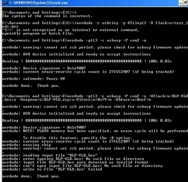
It looks like you are not executing avrdude in the directory the target files are located in. Either cd into the directory holding the target files or give a full path on the command line.
Btw, before going to jump on the programming bandwagon i would like some answers from the masterminds behind this.
1. Are the KD 3x amc based drivers still working with this equipment?
2. Is it possible to program the chip to have lets say 1A high 500mA med and 50mA low AND have a beacon mode added 0,1Hz?
3. Is it possible to implement ramping with memory?
4. Can a potential beacon mode be hidden in the UI?
5. Can this be done also on the 8xamc based KD driver also?
Thanks. :)
Thanks Tido I changed the location of the target files now it only cannot find the .eep file
Probably yes. The last batch I ordered about three months ago was still equipped with ATtiny13s.
Yes. Well, not truly constant 50/500mA, but a PWM level that averages out to this values.
No. This would require one write cycle to the EEPROM for every light level passed during the ramping. Since the EEPROM ist rated for "only" 100,000 write cycles, this would probably wear it out in less than 1000 ramping operations.
Yes. Put it in the extended mode group, but not the main one.
If it is still based on the ATtiny13, yes.
You're welcome ;)