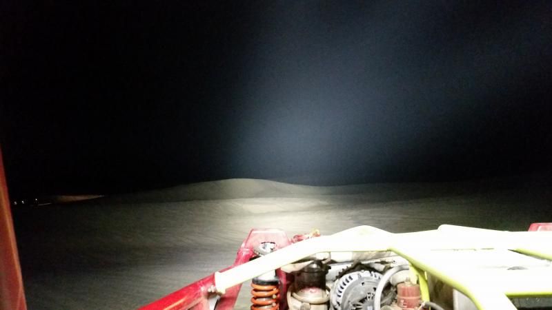
FYI 26.5mm Carclos do throw! Maybe not as good as say a C8 but, they still throw. Here is 24 xml 5000k t5’s, 18 spots, 6 elliptical (4 of my 8” light bars).
Middle dune is around 250 yards. The far one is over 500!
You got your lights working again! Did PTK fix the driver issue or did you have to sub? PM me if you must. I see you’re still running around in that crazed friggin rig of yours, and it apparently hasnt been rolled or blown apart yet. :bigsmile: That is just so bad ass and I love those vids you posted! I just got my vette turning 1.23Gs and finally sticking to the tarmac under WOT, so I feel your LS1 passion when you can keep it running in the power band during most of a run.
Your lights are kicking some major ass, but they are also projecting across a white reflective surface. Still, its very impressive - especially considering the TIR’s. Id never have guessed. I spent a great deal of time researching reflectors, optics, optical efficiencies and radiation patterns for various models. Then I ordered a bunch of samples and took them afield to see how my eyes interpreted each. I already have a pair of 9” reflectored 100W hid cornering lights I converted that pump out 160 degree arc to the sides and 200 yards forward, so I decided to make the LED light bar a pure spot to compliment the existing setup.
Sadly, its shelved at the moment. It turns out that the engineer that designed the drivers figured out a way to slave the thermal throttle controller so both drivers would act as one, which changed my core design. I just havent had time to get back into it.
There is also a parallel project Ive designed for a single driver 16 x XML2 aircraft landing light array for an unlimited category experimental that placed 2nd in national competition. He just wants something that will annihilate the off the shelf lights while saving weight. It will be active cooled with a 1/8” thick copper backbone plate mounted to a CPU sink (8 x XML in each wing with cockpit mounted driver fed via long 18ga leads to each array). Id like to at least get this one up and running (on the bench) first to iron out the bugs because it will be far less complex and not need to be water proof or survive massive G impacts. Lessons learned here will apply to the 40x.
Here’s where I could use some ideas and help:
For the 40x, Im a bit stuck trying to figure out how to mount 40 reflectors in a high G-shock environment without having to machine a retaining girdle to retain, secure and index them. That would cost a fortune to have done. Another member was kind enough to CAD an emitter placement stencil that I can have a shop cut out of vinyl and stick on the sink to allow me to precisely place the emitters and drill the holes for the mcpcb mounting screws. Thats 80 holes to drill and tap. Sheesh! I was thinking about JB welding emitter centering rings to the reflectors. Then gluing flat orings like these to the front of each reflector. Then mounting the large rectangular glass lens in a frame, and using a compression fit of the glass against the 40 reflectors with orings to secure it. I could also probably glue all the reflectors together with JB weld putty from the back side to stabilize it as a solid unit, then the glue mess would be invisible from the front of the unit. Its starting to sound like a redneck project which makes me take a few steps back. There’s plenty of room for error without an indexing girdle and I dont have the orings I linked. I already have all the emitters on copper, drivers, wire, reflectors, copper cut to spec and sinks… so the investment has been made.
ANY ideas would be GREATLY appreciated. Thanks for reading… its late and I tend to ramble when Im tired.
It is probably not cool, and it would be a lot of work but I have been thinking about this light bar a lot, and I have an idea about the lens issue. It all depends on if someone can drill and tap the top your bar or the opening that the reflectors shine through. For simplicity to drill and tap to take the lens, bezel and gasket of a Solarforce L2(whatever). Those would be easier to waterproof than a channel of lights and reflectors. But that might increase the mass that I think you were saying you wanted to keep down.
I could really use some help from someone with AutoCAD experience. I have a friend with a CNC machine that tells me he can cut out all of my parts to complete this project if I can provide input files and material. Can someone with AutoCAD or similar please help me with the drawings/input files? There isnt a whole lot to it. I could provide some detailed specs if someone could please help me.
Another member helped me get this far with a rough draft to conceptualize the project, but he no longer has access to AutoCAD.
There need to be a few revisions to the basic drawing along with a few other simple parts milled out.
Thank you for offering to help me Daniel, but its not all that simple.
The drawing is a reflector placement grid for visualization purposes only.
1) It needs to be revised to make the reflectors equidistant from the edges of the heat sink while maintaining equal spacing between each reflector.
2) The heat sink will use 40 x 20mm Noctigon boards, which will need to be tapped and threaded (2 screws each board) to the heat sink in the center locations of each hole in the drawing. So, the only holes that would be drilled in the heat sink at this time are 80 small threaded mounting holes to fix each Noctigon board (40 boards require 80 small threaded holes to mount them).
3) The reflectors will be retained by a front aluminum mounting plate with 40 holes for each reflector (with a ledge in each hole for an oring and reflector to press against). The mounting plate will be a bit larger than the actual heat sink. I still need to get precise measurements for you. I will probably need to come up with a drawing and post it here for you to get a better idea to CAD from. Each reflector OD is 1.6142”. The holes will need to be slightly larger for differences in reflector size and I still need to find out the ID, depth and width of each shelf in each reflector hole to hold the reflectors in the holes. Also need to measure the thick aluminum plate sitting in the shop.
4) The reflector mounting plate will be fixed to the heat sink with 4 rectangular pieces of aluminum plate to box it in.
Im sorry if I lost you. Its not so easy to explain. This is all preliminary and Im in no rush. Are you still able to help? Ive never attempted anything like this before and know nothing about CNC equipment, so Im not sure what questions to ask the owner. Have you done this type of work before?
To help visualize, check out comfychair’s reflector retaining plate with the ledges in each hole to hold an oring and reflector. Mine would be rectangular with 40 holes as described above.
Thank you so much for jumping in. My day has been overloaded, but hope to find some time tomorrow to get more information.
1) The second drawing looks terrific! (Bottom left - .1206 vertical spacing) should work well and leave enough material since each side will be increased by the width of the aluminum plates to box in the reflector mounting plate. I still need to measure and calculate overall dimensions (H x W) for the reflector mounting plate.
2) I’ll check again, but I think he told me the screw holes for the Noctigons can be done by the machine. That would sure be a huge benefit for precision alignment and save a good deal of tedious work. I’ll also ask if the machine can tap & thread and how that pertains to your drawings.
3) It all looks do-able.
4) More questions and answers that still need to come.
This is all starting to look like it might actually come together this time. Thanks again for your help! :bigsmile:
The sink and aluminum weren’t where I though I had stashed them so I had to go digging. I was happy to find them again! :bigsmile: When you get a chance, can you please see what you can do with the new revisions below?
Revisions:
Sink surface: 25.375” x 5.075”
Reflector opening: 1.639”
Width of reflector shelf to retain o-ring: 0.059”
Hole: 1.521”
Actual Measurements:
Sink surface: 25.375” x 5.075”
Reflector diameter: 1.634”
Width of reflector lip: 0.068”
Reflector ID: 1.498
I’ll take a look at it tomorrow FP, pretty swamped at work. On first glance something does not add up. Shouldn’t reflector interior diameter+reflector lip=reflector diameter? I think I’ll draw a reflector and have you fill out the dimensions of it and the oring/reflector retaining lip/shelf.
Thanks Daniel, Im in no rush. The measurements below are clearanced for reflector fitment and meant to be cut into the reflector retaining plate to secure the reflectors to the sink. The plate is 0.375” thick.
Reflector opening: 1.639”
Width of reflector shelf to retain o-ring: 0.059”
Hole: 1.521”
So…
The hole to be cut in the center of the plate: 1.521 - this will go through part of the plate and stop when it contacts the shelf. I will provide the cutting depth later for the 3D image.
1.521 + Shelf 0.059 + 0.059 (shelf is circular, so on each side)
OK FP, take a look at this revision. I’ve marked in red the problem areas where there’s little material left between the two reflectors and at the edge. You could address this problem by replacing the leftmost and rightmost reflectors in the second row with smaller ones (RGB leds?).The first reflector on the left in the second row is not simmetrical to the second reflector because of space constraints. The dotted lines are the reflector openings (on the inside), the solid lines are the holes. Between them is the shelf for the oring. 0.0784 inch is almost 2mm which I think is a small distance.
Think about it and let me know.