 wight remix
A long time ago I promised I would do a topic to explain to the interested layman the difference between Linear, Buck, Boost and Direct Drive drivers. Well, here it is.
Direct Drive

Direct Drive ‘drivers’ are often referred to as DD or FET drivers. This is the simplest (and sometimes cheapest) design.
As the name implies the it creates a direct path to the LED, just like old incandescent flashlights. A DD setup can be created without a driver by eliminating the driver and simply using a switch to connect an appropriate combination of battery(s) and LED (s). Today this is extremely uncommon. Normally a driver is used to provide modes (High, Low, Strobe, etc) and other functionality such as Low Voltage Protection.
The DD driver contains a control chip and type of transistor called a MOSFET (or FET for short) which is able to turn the LED on and off as directed by the control chip. The modes are achieved by rapidly switching the LED ON and OF. This is called PWM - we’ll discuss the subject of PWM in more detail later in the article.
DD drivers are found in high powered ‘hotrod’ flashlights, daily driver flashlights from quality manufacturers, and cheap bottom-of-the-barrel flashlights. High end DD drivers are often used by people who want to make extremely powerful flashlights that pull 6A or more. When DD drivers are found in low-end flashlights they often contain a much weaker MOSFET which is either unable to handle a high amount of current or simply unable to allow a high amount of current to flow. Often a bank of resistors is added in order to limit current in these drivers to levels considered safe for the cheap MOSFET (or other weak components).
In a direct drive flashlight, the input (battery) voltage must be equal or higher than the LED voltage (‘forward voltage’). The white emitters used in the flashlight hobby are typically considered to be ‘3v’, ‘6v’, or ‘12v’ emitters. These designations indicate an approximate idea of the voltage the LED may need, not a precise one! For example (as of this writing, Jan 2015) ‘3v’ emitters often require between 3v and 4v for proper operation, while 6v emitters often require between 5.5v and 7.5v.
In order to use a DD setup of any kind you’ll need for the input voltage to be slightly higher than the LED’s required voltage (the ‘forward voltage’). For 6v emitters this typically means two lithium ion batteries in series, for 3v emitters this typically means one lithium ion battery. A single alkaline (~1.5v) battery or NiMH battery (~1.2v) will not be able to power any of these LEDs through a DD driver.

In all cases DD setups will cause the amount of current at the LED to vary based on battery voltage. This is somewhat like a traditional incandescent flashlight, but the use of an LED causes the output curve to be much more noticeable.
The performance of a good DD flashlight is very closely linked to the performance of the battery installed in the light.
Advantages:
Cheap.
Possible to achieve extremely high drive current.
No power significant losses in driver (for high end DD drivers).
Disadvantages:
Current varies greatly with battery voltage!
If a resistor is added to limit the current, the efficiency may be lower than a linear driver.
Voltage of the battery must be higher than the LED voltage but not too much above. Proper LED and battery selection are very important.
Linear

This is the equivalent of a direct drive flashlight with a resistor to limit current… But smarter.
The only difference is that the resistor value is constantly adjusted to make a constant current. How is that possible? Well, that’s the job of the linear regulator. Many linear drivers use 7135 IC’s as linear regulators. [The 7135 is available as a 350mA part or a 380mA part. We will discuss only the 350mA part for the purposes of this article.] Each IC will supply a constant 0.35A to the LED. A driver with four 7135 chips will supply a constant 1.4A to the LED.
This is also a very simple design. In the picture above you can see the controller (that produces modes) surrounded by 7135 chips.
Don’t forget! Even though this is slightly more flexible than a DD driver, it’s basically still a resistor to limit the current! This type of driver can never increase a lower voltage input to give the LED the voltage it needs! Like DD drivers, Linear drivers require a higher input voltage than output voltage.
Linear drivers are often a good fit for flashlights using single LED and single lithium ion battery. Ideally the battery may have a ranging from 4.2v (fresh) to ~3v (discharged). An LED which is a good match for this setup may require around 3.2v to 3.5v, allowing for the linear driver to maintain a regulate current (‘maintain regulation’) for a good portion of the discharge.
Quick maths: What is the efficiency of a Linear driver?
Well, the linear driver has a variable resistance that burns off any excess power to reduce the voltage to 3V for the LED. That means that with a fully charged battery the efficiency will be lower than when the battery is discharged.
Efficiency=VLED/VBattery
Fully charged: Efficiency=3.3V/4.2V=78%
Half discharged: Efficiency=3.3V/3.7V=89%
Almost discharged: Efficiency=3.3V/3.3V =100% (Approximation, not taking into account all the parasitic resistances.)
When the battery voltage becomes too low, the linear driver will reduce the resistance to its minimum, to power the LED until the end (but dimmer).
In all cases the output voltage of the linear driver will be lower than the input voltage. There is a margin by which the input voltage must exceed the needed output voltage, this margin is referred to as the “dropout voltage”. For example, the dropout voltage of a single 350mA “7135” IC may be 0.12v. In this case with an LED which needs ~3.3v the 7135 will lose regulation at around 3.42v. At and below 3.42v the 7135 will simply give the LED the input minus 0.12v, so once the battery is depleted to 3.10v the 7135 is only able to supply 2.98v because 3.10 - 0.12 = 2.98.
“Why can’t I use a linear driver to supply a ‘3v’ LED from two lithium batteries in series??”
Let’s do the maths:
Efficiency=3.3V/7.4V=45%!!! More power is wasted in the driver than fed to the LED! That will reduce battery life and the driver will overheat. On top of that the 7135 chip will fail above 6V… The 7135 IC is rated for approximately Vin - Vout = <7v, but the primary limitation is how much power the IC can dissipate. In general input voltage should be no more than a volt or two higher than the required output voltage.
Further reading:
AMC7135 datasheet
Advantages:
Simple
Robust
Efficient if used in a single-cell single-LED configuration for 3v LEDs (or 2-cell config for 6v LEDs)
Constant current for much of the discharge of the battery
Disadvantages:
Voltage of the battery must be higher than the LED voltage but not too much above.
Buck

This is also called a step down driver and is part of the SMPS (Switched Mode Power Supply) family.
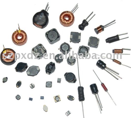
It is easily recognizable thanks to the big inductor. Sometimes the inductor is a black surface mount device while other times the inductor may be a large colorful toroid (donut shape) with copper wrapping:
This is a more complicated design. I won’t go into details as it is well explained on Wikipedia .
In a nutshell, it uses an inductor and other components to step down the voltage. Compared to a linear (7135) driver, the Buck driver will have a fairly constant efficiency, even with a battery voltage much higher the LED voltage. It can be used to power a single LED from a significantly higher input voltage. For example, a ‘3v’ emitter could be powered from 2 or more lithium ion batteries in series. Efficiency is typically between 75% and 90%. That depends largely on the quality of the design.
This type of circuit is used widely in consumer devices because of it’s efficiency. It may be found in PCs, TVs, Smartphones, Tablets, etc. Most of those devices use a ‘voltage controlled’ buck circuit, while for our purposes a current controlled buck circuit is almost always utilized.
In operation current controlled buck drivers share many similarities with current controlled linear drivers. Like linear drivers, buck drivers can only decrease voltage, so they also require a higher input voltage than output voltage. Current controlled drivers monitor the output current and provide whatever output voltage is necessary to achieve that current… within their abilities. Buck drivers are also similar to linear drivers in that they have a dropout voltage. For many buck drivers this can be much higher than we are used to with linear drivers. It’s common to see dropout voltages in the order of 0.5v to over 1.0v.
Typically buck drivers are used in scenarios where input voltage significantly exceeds output voltage. In this way the dropout voltage is never approached, allowing the buck driver to maintain tight regulation throughout the discharge of the batteries. Due to their good efficiency the use of multiple batteries may extend runtime vs a linear driver where less batteries would be used.
Like the other driver topologies (such as linear and ‘DD’), cheap buck drivers are also available. Typically these cheap drivers provide no Low Voltage Protection. Without proper care this configuration can easily damage batteries! For example: an LED which needs 3.3v being driven by a buck driver with a 1.0v dropout using two lithium ion batteries in series. The driver may be able to power the LED until the two batteries measure only 4.3v total, or 2.15v per cell. This is well below the maximum safe discharge level for a lithium ion cell. Therefore in the case of a cheap driver with no LVP ‘protected’ cells should always be utilized along with any other appropriate precautions.
At extremely high currents buck drivers can misbehave in technical ways, damaging LEDs. Special design considerations are required in order to minimize things such as ‘output ripple’, startup or shutdown spikes, and other factors.
Advantages:
Can be used with batteries that have a voltage much higher than the LED voltage. For example three lithium batteries in series will produce about 11V. In that case you need a Buck driver to drive an LED that needs ~3V.
Good efficiency
If well designed it can produce a low mode which is truly free of PWM. That’s good for sea sickness and for the LED efficiency. (More on that below)
Disadvantages:
More expensive.
Voltage of the battery must be significantly higher than the LED voltage.
Bulky.
Cheap buck drivers may be able to overdischarge cells.
Potential for badly designed or misused buck drivers to damage LEDs at high currents.
Boost

This is also called a step up driver and is part of the SMPS (Switched Mode Power Supply) family. Like a buck driver, the boost driver is easily recognizable thanks to the inductor. Sometimes the inductor is black. This is similar the the Buck driver but as its name implies it will increase the voltage.
This type of driver is often used in flashlights which have one or two AA/AAA batteries. Two AA batteries in series will have a voltage range of approximately 2v to 3v. A 3v LED might need ~3.3V, so in order to drive it from 2xAA the voltage needs to be stepped up. There is no other solution!
I measured the efficiency of a single AA flashlight and typically found:
At the battery: Vin=1.2V ; Iin=2.2A
At the LED: Vled=3.2V ; Iled=0.35A
Let’s do some maths:
Efficiency=(Vled*Iled)/(Vin*Iin)=(3.2*0.35)/(1.2*2.2)=42%!!
That’s really bad! Well yes, but it’s hard to step up a voltage as low as 1.2V… The efficiency is better at 2.4V (2*AA). That means that if you choose a 2*AA flashlight you’ll get more than twice the runtime for the same brightness! That’s definitely something to consider.
The boost topology is also sometimes used to power a string of LEDs. For example 3x 3v LEDs in series will need about 10v. A boost driver may be able to drive them from a single lithium ion battery.
Boost drivers which are used with higher input voltages (such as 3v, 10v, 20v, etc) are often able to achieve much higher efficiencies than their low-input-voltage relatives. It’s possible to achieve similar efficiencies to buck drivers in the right scenario, such as driving 30v worth of LEDs from a 16v source.
Advantages:
Can be used with batteries that have a voltage lower than the LED voltage.
If well designed it can produce a true PWM less low mode. That’s good for sea sickness and for the LED efficiency. (More on that below)
Disadvantages:
More expensive.
Doesn’t work if the battery voltage is higher than the LED voltage.
Bulky
Cheap boost drivers may have rather harsh PWM.
What about PWM?


PWM means Pulse Width Modulation. It’s a way to control the brightness of a flashlight by rapidly switching it on and off. If it doesn’t switch rapidly enough (PWM frequency too low) it can be unpleasant to the eye. The picture above was taken while rapidly moving the flashlight to show the effect.
Something that is often overlooked is that an LED receiving PWM will be less efficient than the same LED receiving an equivalent constant current. Why is that?
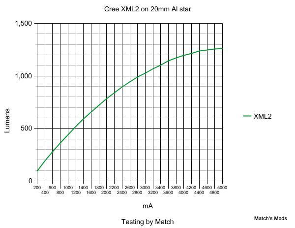
Well, as you can see above, the lumen output is not linearly dependant to the current. Let’s take an example:
Driver 1 is driving the LED at 2800mA at full mode. This driver also has a medium mode that is a duty cycle of 50%. That means that half of the time the LED is OFF and it’s half of time ON. We will get half the lumen of the full mode: about 500 lumen. On average it’ll consume 1400mA.
Driver 2 is also capable to drive at 2800mA. When in medium mode however, it uses a constant current of 1400mA. The average consumption is the same as Driver 1. The lumen output however will be about 600 lumen! That’s 20% more lumen.
All this to say that in a flashlight which uses constant current on all modes the LED will operate at a higher efficiency than in a flashlight which uses PWM. If the driver efficiency is the same between the two lights the constant current flashlight will be more efficient!
*
In conclusion, some basic suggestions:
If you have a flashlight with a single 3v LED and a single lithium ion battery then get a Linear driver.
If you have a flashlight with one or two NiMH/Alkaline batteries, then you must use a Boost driver.
If your battery voltage is much higher than the LED voltage then get a Buck driver.
If you want to see the same thing explained by someone else, I invite you to read this.
Thank you for reading this. I hoped it was helpful to you and if it was please say thank you!