V2 of the 17 released! (15 in progress, will be done in the next few days)
-The MCU has been switched over to the slightly cheaper 12F617
-The code has a few new features, this includes battery monitor and a flashing indicator LED that can be placed under the switch (and replaces the main LED locator beacon) there is also some changes to the way strobe operates (however its still entered via a triple tap).
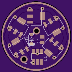
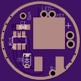
-The secondary emitter (switch indicator) runs from pin 6 and uses those 2 tented via’s you see, they’re tinted to help prevent shorts in applications you dont run one, scrape the mask to solder to them. You should even be able to solder an 0603 LED direct to the via’s like a pad if your light has a switch at the top of the driver level.
I will make anice little flow chart of the UI (and a new video showing this final version) later today / tonight.
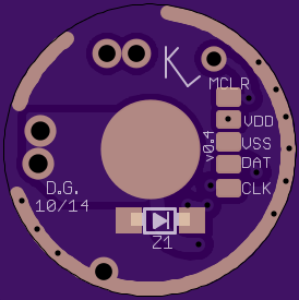
Note the code linked above DOES NOT run on a 1822, I will be hosting the new 617 code in soon as everett has a chance to check it over (tonight), it runs but I want him to make sure he’s cool with the credit I put and the comments and stuff I added. Everett had already added lots more comments to this new version and I took it ever farther, hopefully its easy for you to mod. You guys can download MPLAB and check the code out now even without having a picKIT to flash it yourself. If you want to do this I will flash code you modify and send me. Again please do not re-host code you modify but you may make any changes you wish and use it in any personal applications.
I think this will be a very popular driver once folks start using it and giving feed back. It probably taking off slow for 2 reasons:
Past new boards were purchased by many of us as soon as they released and then new revsions had to be made to fix issues. I think that made many of us gun shy.
This is a new MCU for BLF'ers (Well, they may have drivers with this MCU, but they don't know how to program them yet.
I just ordered 3 17mm boards. Once I get them working, I'm sure I will be ordering many more. I'm off to find the PIC MCU's and will order some. Do you have a recommended source? The rest of the parts I already have. I'll report back on progress soon.
A side note. I don't think you should feel you have to provide these drivers as cost. I think most folks here feel your time is valuable and have no issue with you including something for you time in the price. It might even make folks feel better about taking the plunge into this new driver.
Thank you very much for your efforts on this project. It's an exciting new development for your hobby. Hang in there bro :)
There are several different SMD 12F617's listed on Mouser. They have the following suffixes: E/SN, E/MS, I/SN. Do you know which one is best for this driver?
An AliExpress vendor is selling 50 pieces for $33.06. They are I/SN's. Will they work on this driver?
So compared to the Attiny13a, the 12F617 has twice the program memory and twice the data memory. Program memory can be flashed 100.000 times (10,000 for Attiny) and will be retained for more than 40 years (20 years for the Attiny). Standby power usage is super low (50nA vs 24uA for the Attiny). All that means its much bette long term for our hobby.
The 12F617 doesn't appear to have EEPROM memory. Do we use the EEPROM memory in the Attiny's?
The 1822 has even better specs. Was the only think you needed to change was the FW? It appears that the pinout is the same for both the 617 and 1822.
12F617-I/SN is what I use, tho the letters dont mean much in our application, I believe any of the soic8 package ’617’s would work. They’re temp rating and stuff like that.
As for the ones @ AE, they list as SOP8 but when I google SOP8 vs SOIC8 they seem to be classified as the same thing (so maybe just slightly different size / width / something)I’m not sure.
The FW for the 617 was further developed and the 1822’s are about $.30 more per piece. Also running these on the 617 all my drivers use the same MCU
I ordered them from Ali. I won't need 50 as I don't plan on selling drivers or chips. They should be fine if they are really 12F617-I-SN's. I'll keep you posted.
In addition to Cereal_killer, I wanted to thank tterev3 for making this driver possible. Getting excited to start playing with them and with programming these PIC's
By the way folks, the PIC programming kit is now only $19.80 at Banggood. Mine arrived very fast. I haven't used mine yet, but it looks good.
> I don’t think you should feel you have to provide these drivers as cost. …
> your time is valuable and have no issue with you including something for you time in the price.
> It might even make folks feel better about taking the plunge into this new driver.
I received the 12F617 I SN's Saturday. They look just like in the picture here. Also have the 17mm boards from OSH Park. Not sure when I will get much time to work on FW though. Got a car project underway right now. Hope to wrap it up fast though.
Just finished up installing the first one of these I’ve Zener modded and it works great. Since voltage monitoring doesn’t work once the Zener is added I went ahead and used the original 1822 to have all the strobe options and adjustment (originally switched to the 617 cause that version has battery monitoring but not the extra strobes) the 1822 version doesn’t have the battery monitor but that doesn’t matter in this application. Again the pinout is exactly the same so its a direct swap.
Note the Zener gets REALLY hot while it’s connected to the PK3 since the current is actually higher than the 200ohm resistor allows while it’s running, careful, I wouldn’t leave it connected very long and don’t touch the Zener.
I’ve just finished up a new board, 17mm and 10x7135. It runs a 10F322 which has 2 FW’s available (thanks again to tterev3) One is a very simple clicky FW with 2 modes plus a slow signaling strobe, one of the 2 modes is a user configurable level (set with clicking to start a ramp then click again to set ramp position) the other mode is max followed by a slow flasher. You can see the UI here including a video and a link to DL from toykeeper’s hosting (havent personally verified the code is good there but I’m sure she knows what she’s doing)
The other code is a version of the same Ultimate Flashlight Code for the 15 and 17dd_PIC’s but on the 10F322 and written in C for all of us!
I’m waiting till my first samples get in before I share the project but this should be a very versatile driver.
The Zener pad there doesnt get populated for 1cell builds, its just there as an option (I’m also going in to add zener pad’s to my 15 and 17 boards tonight too)
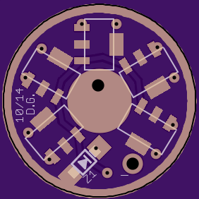
Thanks man! One final change I made was to place the zener over the top of the MCU instead of at the 200ohm resistor [to GND] like in the pic I sent you. I also went ahead and got the driver’s updated to allow the zener to stack over the cap (now on the back of the board) for a better mounting solution- the links in the OP of this thread are the most current (and final) revision.
I’m gonna go ahead and post the pic’s I took in one of the Y3 threads, I think its more fitting there.
you’ll notice there is only the one decoupling cap, not the “new” location Comfy found for the AVR drivers. I have verified this isnt needed on these PIC drivers!
sure, that woldnt be a problem at all now that I’m using Eagle with the proper technique, only a single operation would be needed- to expand the milling layer, poly would automatically take care of the rest. Doing so sould also allow room for programming pad’s on the bottom of the board.