Thanks for the compliments folks! …I agree, the triangle is clearly the source of this driver’s Qi.
@ WarHawk-AVG - the FET’s plastic package (tisk tisk) is actually smaller than the ATtiny13A’s package. It’s not as wide or as long. When you include the length of the metal tab and pins I think the FET ends up being approximately 0.5mm longer, that’s it! They definitely fit on each other’s pads.
Yes, I can easily increase the size to whatever is appropriate. 20mm, anything else? I’ll take a look soon. I also took an unsuccessful stab at 15mm following a pre-release request. I was unable to get all the components to fit on one side in 15mm as I recall, so I moved the 3 lowest profile components to the bottom here.
If you choose to use 19.2k for R1 instead of 22k you will need to adjust your LVP in the firmware before flashing. If you are using a pre-flashed ATtiny13A with LVP you must use 22k for R1. 19.1k will result in LVP allowing VERY low voltages. I highly recommend that you use 22k and be done with it.Digikey / Mouser / Farnell (for the rest of the world)
Some of our more determined friends here may prove that a DPAK FET can be made to fit upside down with some major filing. Basically the same filing you’d use to install it on a Nanjg-105c. IMO it won’t be worth the effort when you can install the DPAK FET on a Nanjg-105c or you can just drop in an LFPAK56 FET on my PCB no muss, no fuss.
If anyone wants to contribute any good eBay / Aliexpress links I’m all ears. Not everybody can buy through these distributors.
The problem with eBay links is it’s quite often hard to find the relevant data sheet for that particular FET and Rds on values can vary from absurdly low 1-2 mohms to more than 10mohms. Mouser at least gives data sheet links for each FET listed so you know what you are getting and will show the values for 4.5Vgs and 10Vgs as well as showing a graph from which you can interpolate behavior between 3-4V. Once again, the eBay crap shoot.
As you mentioned Vgs is important. In this case the Vgs graph just stops at 3.75v (where it’s still only <5milliohms but appears to be close to going vertical). Frankly that looks pretty similar to the FET I’m using as well as pretty similar to the DPAK AOD510.
Actually….
What about PSMN1R2-25YL? It’s late at night and I can’t go find the answer to how much gate charge the ATtiny13A can handle, but I think that that FET has a low enough gate charge (Qg) at <5v. The Rds(ON) figures look great to me, much better than the other FETs we’ve mentioned so far. I suspect that PSMN1R2-25YL would not be a good choice for Zener builds but might be very good for regular builds. I see them on eBay and I see that Mouser has them on order. Farnell has PSMN1R2-25YLC in stock, that’s not the same thing so watch out for that!
So, uh, here’s a thing I’ve never seen before…. http://cdn.vicorpower.com/documents/datasheets/Picor/ds_PI5101.pdf
It’s not actually smaller than LFPAK56, but the specs are crazy. Also they cost $5/ea, heh. And this is the only part I see on Digikey with that form factor.
So Wight, will that Picor FET replace what we’ve been using, with much lower Rds on? Looks like it’d be a very neat and trim package to produce a slimline driver with great characteristics.
And yes, really like the looks of your new driver! I have 4 of those FET’s, will probably be trying a couple of those…just ordered a bunch of re-stock in the traditional caps and resistors wouldn’t you know it!
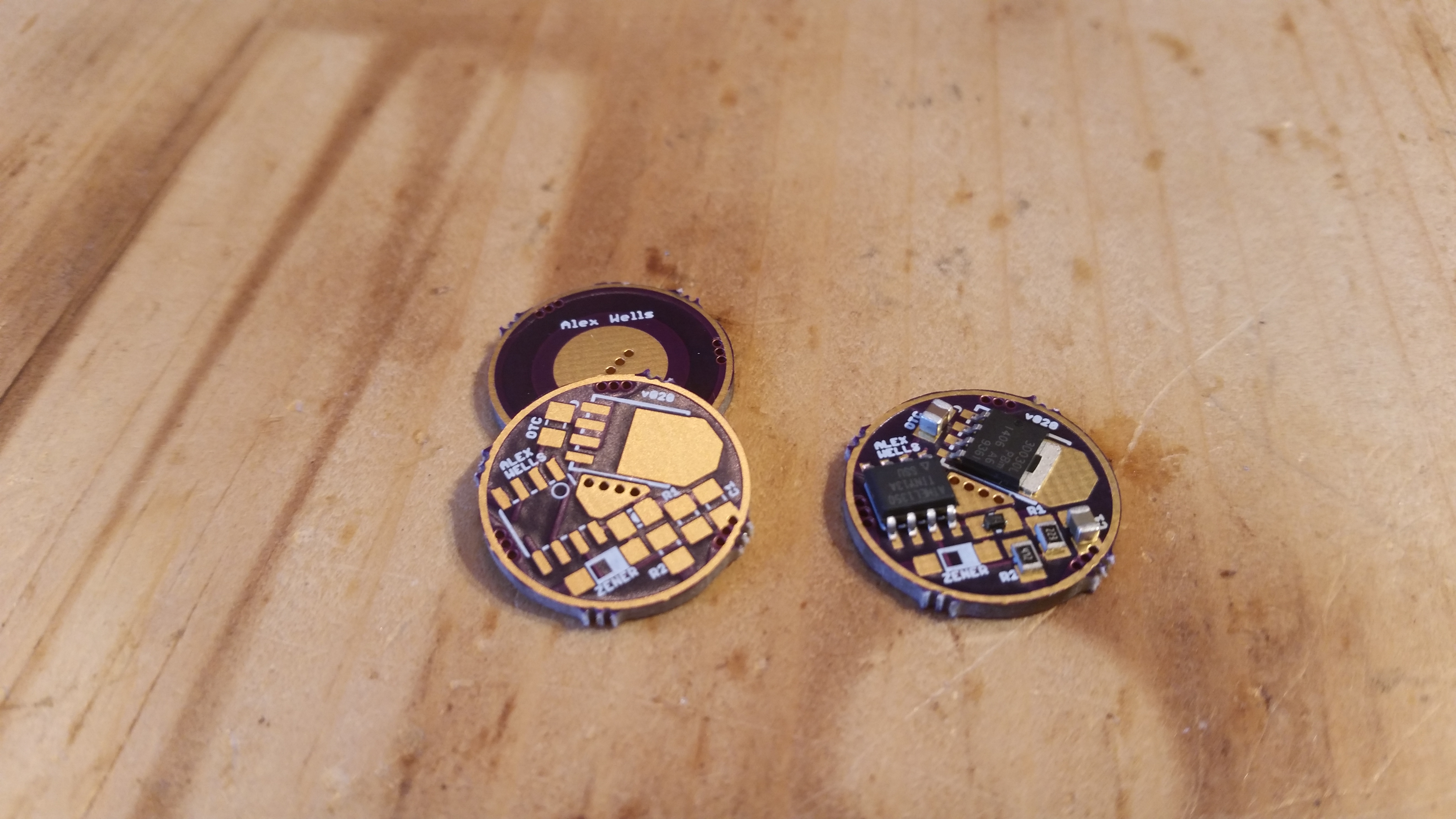
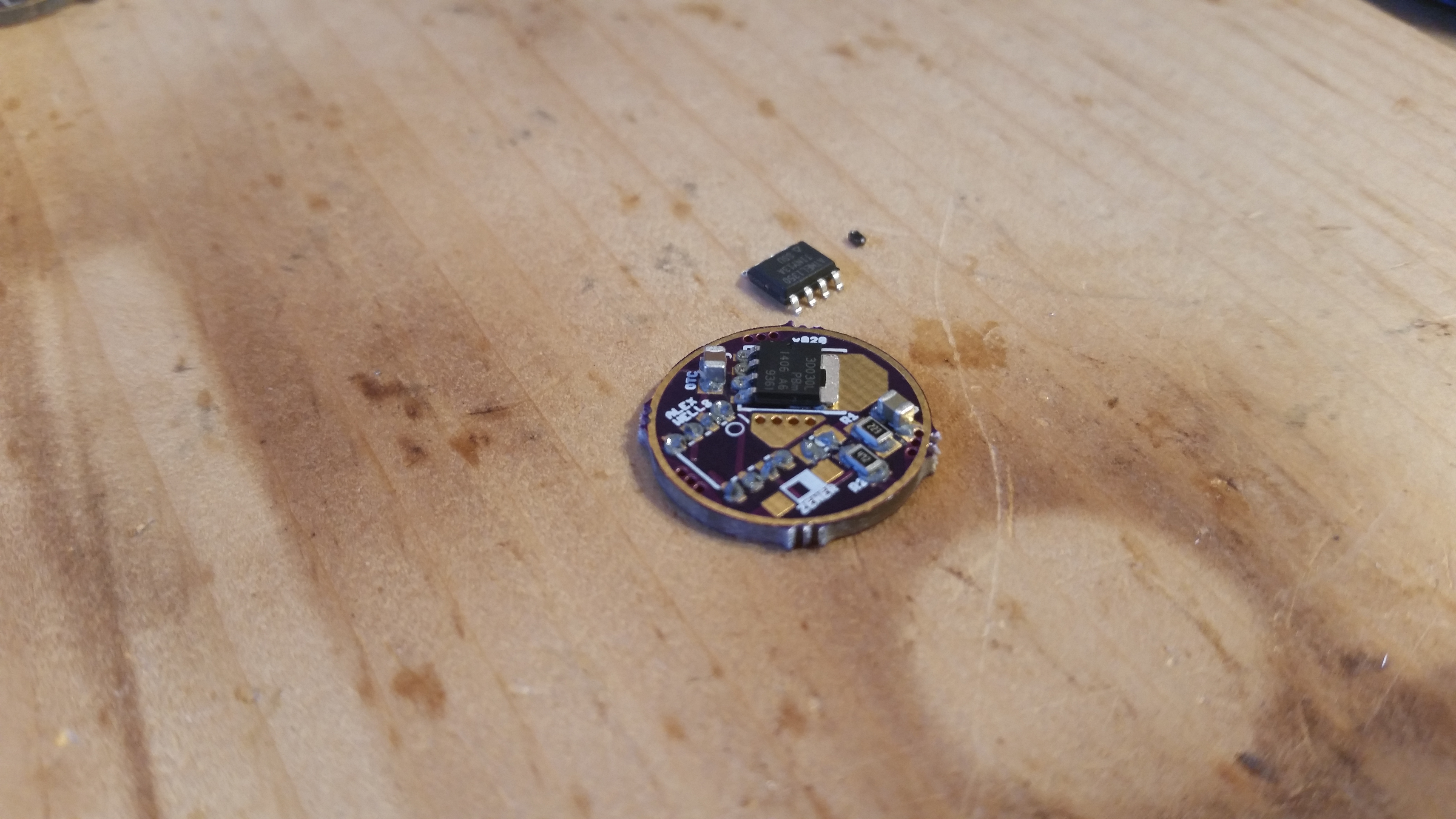
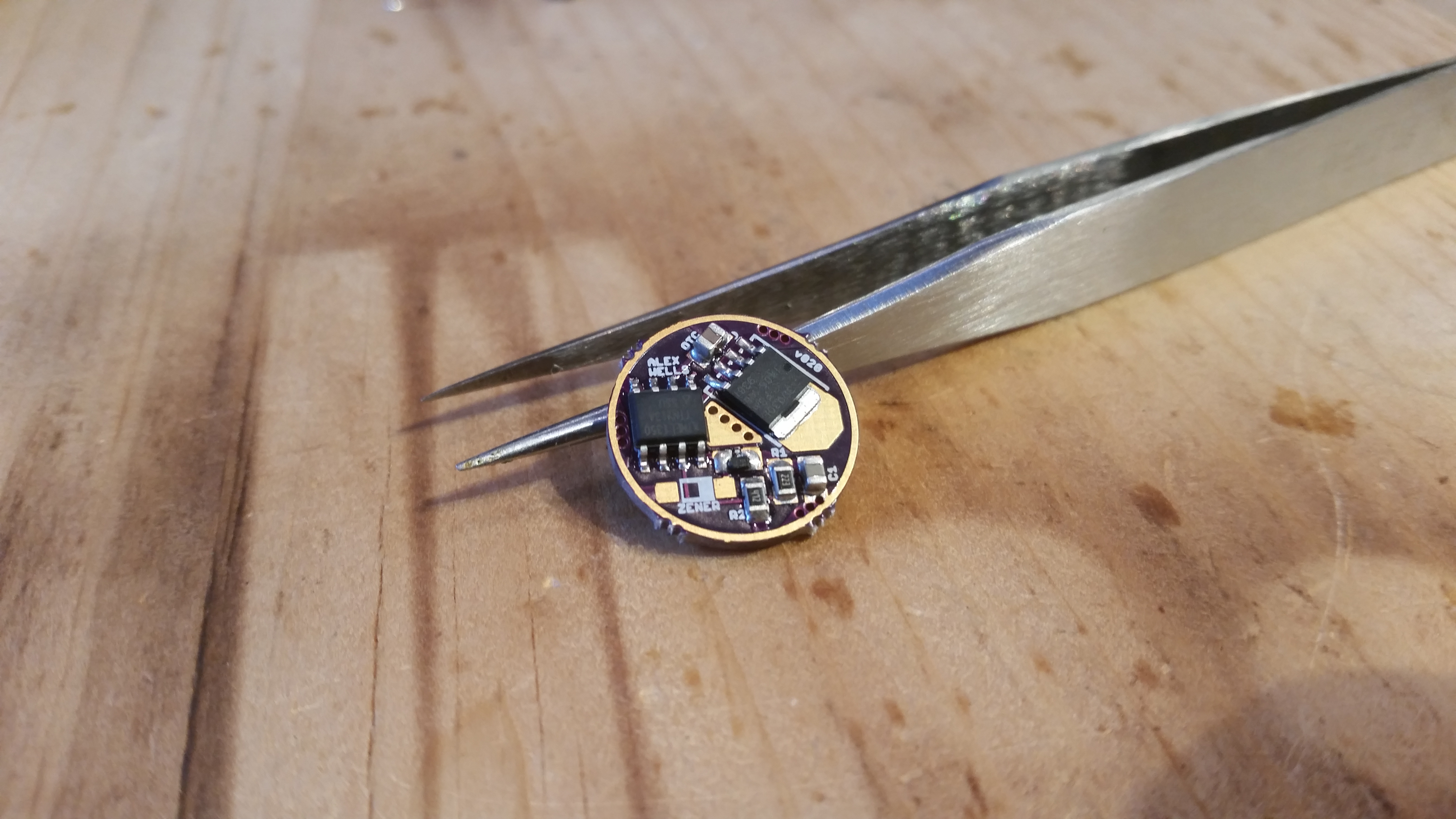
You’re welcome. I’m using a syringe of Kester EP256 (Easy Profile 256) from CML Supply. If you click through to the big version of the first pic in the OP (the picture with the tweezers) you’ll see that my application isn’t really perfect - R2 has a lot more solder than R1. Due to the low quality of the picture what you probably can’t see is that I reworked D1 with my soldering iron after the reflow. I was out of normal sized diodes so I used the tiny SOD-723 size. It blew around during the reflow process and was hooked up correctly but kind of askew and unattractive. That’s why those pads appear slightly shinier. To better illustrate, here are 3 pictures showing the components laid out without paste, then the components partially placed after adding paste with the syringe, and finally the initial results of the reflow (before rework). Sorry about the focus in the second pic, it’s on the back of the PCB rather than the front.
The Picor is fairly long/big and fairly expensive. It’s also a no-leads package, making it potentially difficult for novices to work with. I think that it won’t replace anything for now, but we should keep it in mind in case the need for such an extreme FET should come up. There is also the supply issue: AFAIK there is literally only this single FET which uses that package. If Picor stops making production runs of these things then any designs based on it are squashed. Frankly I haven’t even looked at it that closely, I suspect that the specifications probably preclude this use anyway. Yeah, take a look at the maximum Drain-to-Source voltage: it’s 5v. It wouldn’t be able to handle the spikes from single-cell DD use I think, and it certainly can’t handle 2s use.
Heh, good point RBD. For voltage monitoring on the Zener version (which I have not built) I’d think you’d want R1 to be in the 47k - 50k range. EDIT: (for 2s applications)