Yup, what he said. ![]()
This one should be fairly straightforward.
Yup, what he said. ![]()
This one should be fairly straightforward.
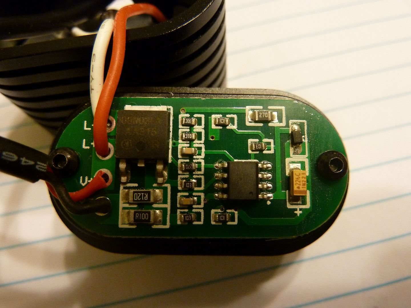
Remove both of the R100 and R120 and use three R050, you will get approximately 2.94A @ the battery.
Or, stack two R050 on top of either R100 or R120 and you will get approximately 2.86A @ the battery.
Anyone is welcome to check my math though.
Are those sense resistors or limit resistors? Is that driver even regulated? What is the current at 4.15V, 3.8 V? It just looks more like a DD driver with modes to me.
Well at 3.89v I get 1.53A. Does that help?
-Garry
It looks like to me a dd driver with those 2 resistors going from ground to the source on the fet. Limiting like that.
hmm, I’d probably take the .100 off and put in a .120- then lay a couple of .120s on top of that, if that’s all you have. Should give you ~3.2-3.3a or so.
Aiming at .032 for 3a from my math anyways, at 4.06v.
Try the four .120’s and see where it’s at… If you have a .180 that, stick that in over a .120 and it should be right at 3 according to my calculator least.
I’m sure wight will be in here
Good point. There is no torroid there, I guess it is just DD driver. If it is really DD driver you can just simply bridge the resistors.
Like RBD and FFT said, they appear to be current limiting. If they are, their resistance in and of itself is limiting current flow. Are there any components on the other side of the driver (Other than the switch)? Also, I can't follow some of the traces due to part of the board being in shadows.
4.06V - 1.8A
3.89V - 1.53A
Pretty sure it is DD driver then.
The use of the resistors would still be the same but the values might be different since those resistors just add to the total of the circuit. In other words halving the resistance probably won’t double the current. Also, if it’s DD then it’s not regulated across the battery charge so output will start to dim from the moment you turn it on. Don’t know if you care about that.
I’m no EE and could well be wrong but if not you might be better off just replacing it with a 3A Qlite or whatever firmware 105C floats your boat. Then you would have better efficiency and consistent output over most of the charge cycle. Better still would be a Led4power LD-01 which is even more efficient in the low modes than a nanjg type and doesn’t have pwm. It’s not as cheap and has fewer firmware options but I can’t wait to try one out for myself. If the board has an integral switch then another option would be to pull the resistors and the FET and replace them with an 8x7135 slave board and keep the existing mcu and firmware.
As it is that driver seems to be running with one foot on the gas and the other on the brakes.
Hmm . . . interesting idea, but I'd need my hand held the entire time as that is well beyond my ability to handle. Can you sketch up a diagram on how I'd wire it up?
Thanks,
Garry
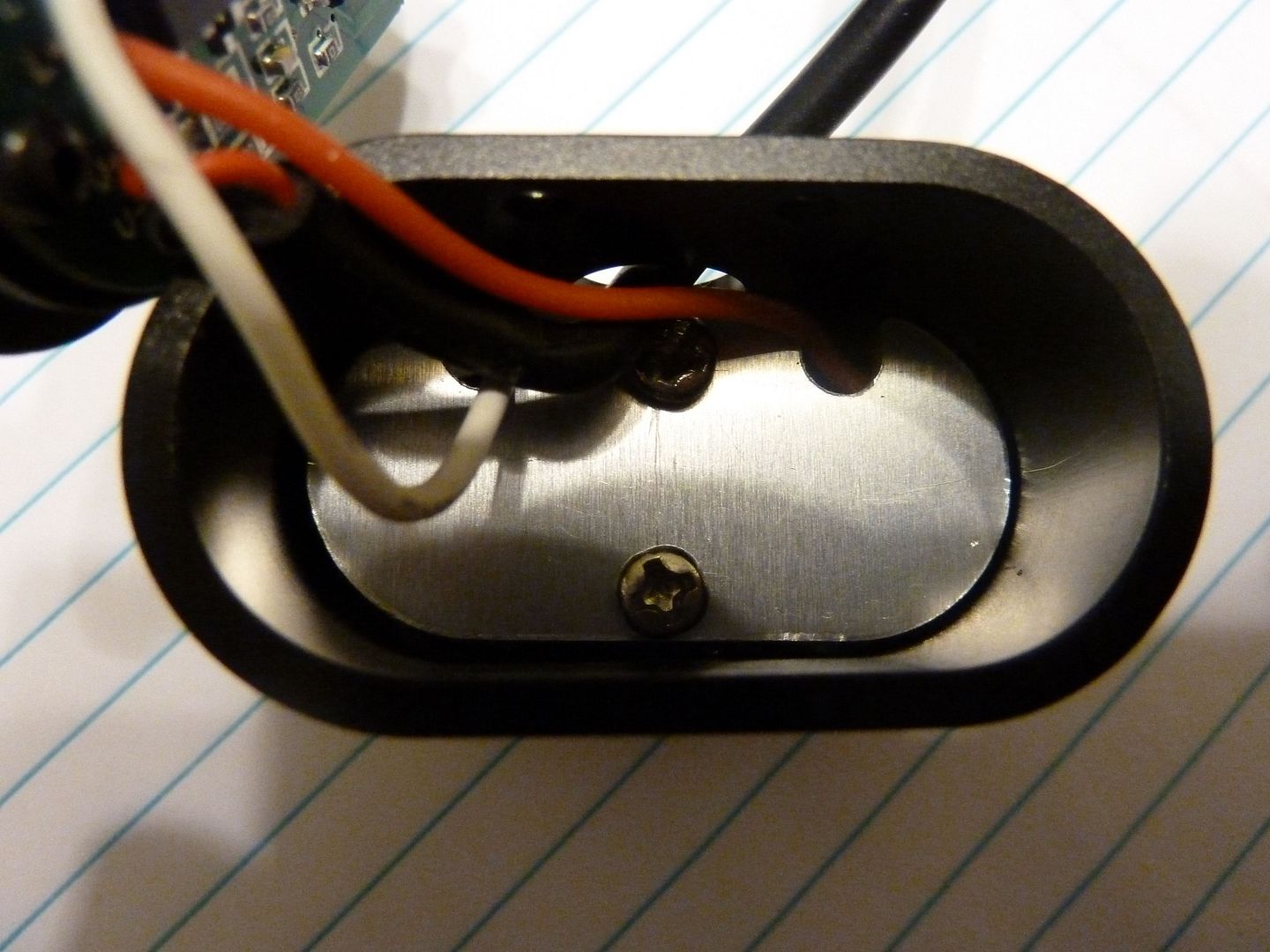
Here is another photo of the driver showing the traces a little better:
(I didn't post this one because the FET wasn't as legible.)
-Garry
I can’t see any photo.
I would just bridge it if it was me garry. I mean think your pushing 4s in parallel into two xml2 u2 emitters in parallel from the looks of it. You can run in medium, low modes and have the high for when you need it. Maybe reflow onto a couple of noctigons and redo the tim. You should have plenty of light in the lower modes.
Or put in the 120s you already have and see where high takes you. That’s the cheapest way right now. Those u2 aren’t going to blow up on dd- just keep it in the lower modes until you can get the noctigons and tim mailed out to you
Just my 2 cents anyways… ![]() * disclaimer I take no responsibility if those emitters are mounted badly or have no pill and go blue on high
* disclaimer I take no responsibility if those emitters are mounted badly or have no pill and go blue on high
But seriously the four 120s should be good even with crappy sinks, that’s less than half what those leds can take… You can then add more resistance or take away after playing around.
Yes. And… now I can also see the photos… Dwarf mischief ![]()
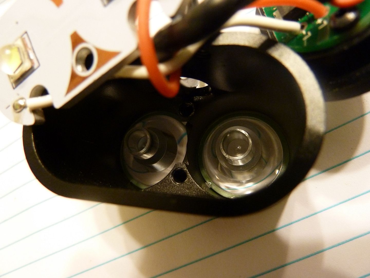
That's all I have for heatsinking in stock form! Emitters on a 2mm thick aluminum board only making contact at those triangle shaped contact points (not even around the edge of the board!). I plan to fully "pot" the area behind the board out to the driver. Even then I don't want to produce a huge amount of heat.
-Garry
^ At least it appears to have a copper layer to spread heat and transmit to the host. Might not be all that bad. Need to check for thermal sag to know.
I looked at the photo gallery. It looks like those resisters have traces going to more than just the FET Source Pin. Are there any components on the switch side of the board?
Yeah I would bridge it man… You don’t have to worry about the limiting resistors going out. I think, well from what I’ve gathered here on the forums… That’s not the correct way to limit power. I’m no expert by any means but I know what those emitters can do. Try bridging it and put it on medium- check the heat. The pwm should keep it cool and you’ll have high for blasting your buddy in the face when he looks back
*Edit yeah 4wheel guess could cut the trace to the source and ground the source on the FET… That would be the safe way to do it
Ugh! Do I really have to tear it down again? I figured the backside didn't look like it had anything important. Should have known I should have taken pics. Will try to get to it soon (like tonight).
-Garry