Crap, I had no clue that zener mods were that bad with e-switch lights.... Yikes! Sure it was mentioned (I guess?) but totally missed it. Thanks wight for starting that thread and new board design!! I'll be sure to susbscribe and follow. Hhmm... Means the Y3 MT-G2's had that issue? Oh boy... Deleted - no harm intended Tuff to keep up with all the driver goin's on's...
This looks very suitable to me. Do you see any spec you do not like?
Not in particular, but some vary.. have a look.
PSMN3R0 / PSMN6R0
Drain to Source Voltage (Vdss) ------------------- 30V / 30V
Current - Continuous Drain (Id) @ 25°C ---------- 100A (Tc) / 71A (Tc)
Rds On (Max) @ Id, Vgs -------------------------- 3.1 mOhm @ 25A, 10V / 6.5 mOhm @ 20A, 10V
Vgs(th) (Max) @ Id --------------------------------2.2V @ 1mA / 1.95V @ 1mA
Gate Charge (Qg) @ Vgs --------------------------46.4nC @ 10V / 19nC @ 10V
Input Capacitance (Ciss) @ Vds------------------- 2939pF @ 15V / 1088pF @ 15V
Power - Max ---------------------------------------91W / 58W
Mounting Type Surface Mount (same)
Package / Case SC-100, SOT-669, 4-LFPAK (same)
Supplier Device Package LFPAK56, Power-SO8 (same)
When you look at the Vgs graphs the Vgs advantage of the FET you selected (PSMN6R0-30YLB) becomes even more clear in my opinion. AFAIK lower gate charge is desirable, also lower input capacitance sounds like a good thing. Dissipation (the 58W number) doesn’t really matter in this context, we should not dissipate anything significant in the FET. The Rds(on) seems like it may end up 10-15 milliohms higher in the Vgs range we actually use. That may not be ideal, but I think it’s acceptable.
Hey wight, was perusing mouser and found the PSMNOR9-30YLD with an even lower Rds(still below 2mOhms at 3V) but it runs the price up. Maybe a GB for a bunch and adding normal postage to that might be reasonable.
There is no such thing as normal postage out of US, unfortunately.
When I did the GB for the tiny 10 postage was pretty cheap. Photo envelopes were only $.50 and postage and paypal fees worldwide were only $1.15. These are more expensive FET’s so it makes more sense to do a GB for a bunch than ordering onesie-twosie. Still, it would makes sense to try them out and see if they’re worth the added expense.
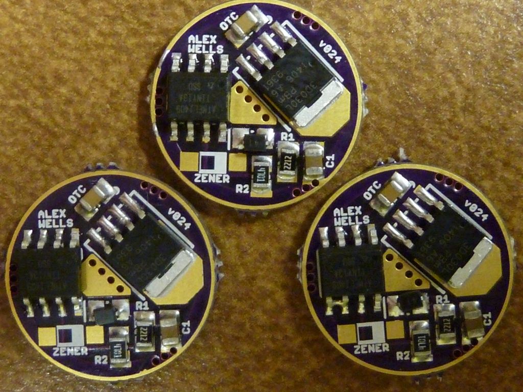
My first batch run, first homes:
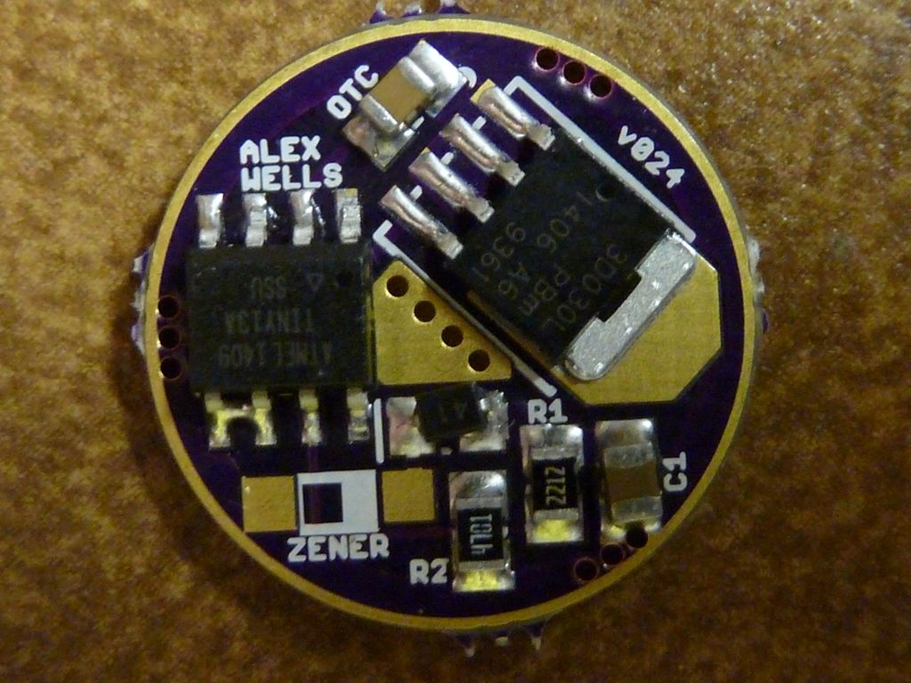
Oops, already fixed the bridge between pins 5&6 on the ATtiny13A:
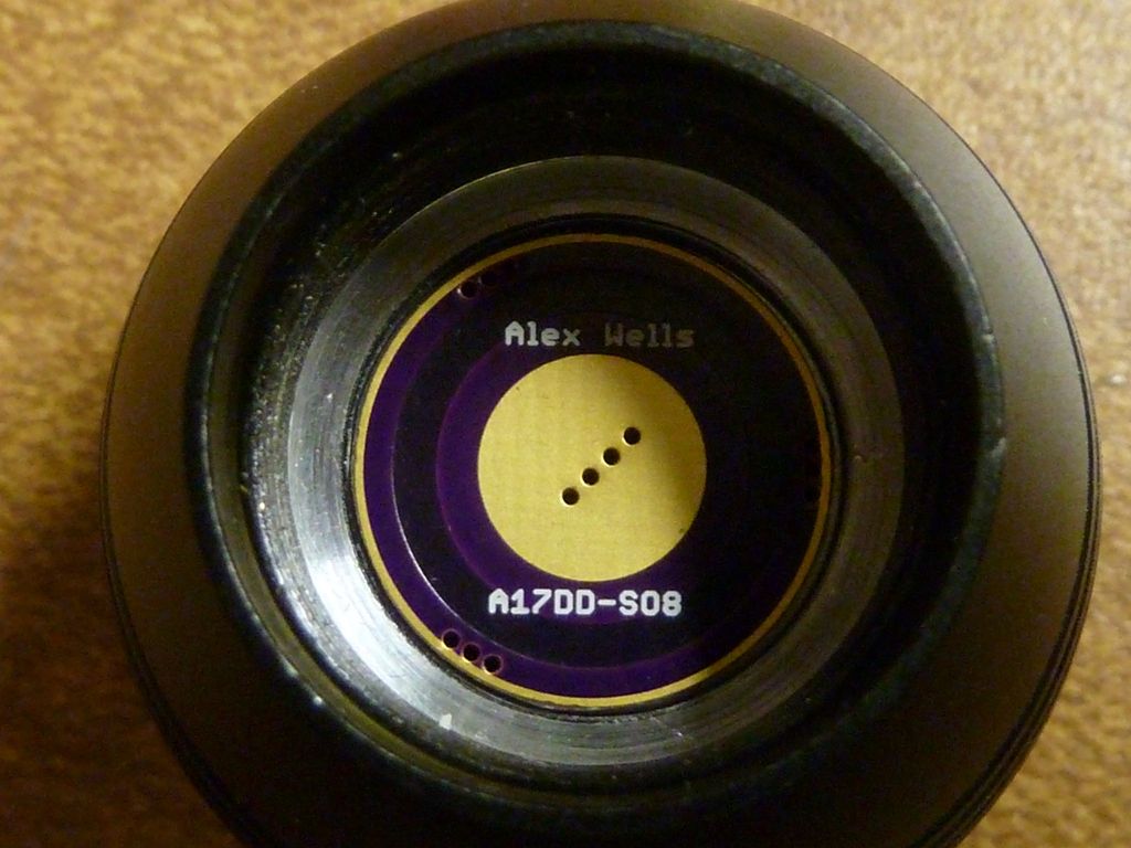
X6 BLF Special Edition:
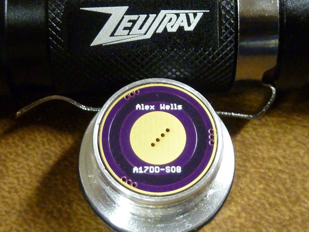
ZeusRay zoomie:
This looks like a good FET. I don’t see any downside other than the price; I think all specifications are either acceptable [with no impact on performance] or better. The low Rds(on) through 3v looks especially interesting. Only testing will tell us whether it’s worth an extra $1/ea in general, but I’d say that this FET has better specs than PSMN3R0-30YLD.
Thanks for the pics Tom E, your builds look good!
Sweet driver isn’t it? ![]()
Y’all would come up with a better FET immediately after I ordered 25 of em!
I did bout all the continuity tests I could think of but guess didn't check for shorts. Only way I noticed the short on the MCU was by looking at the picture I took - funny....
Not happy yet with the reflow job - parts getting moved, sometimes blown off, etc., by my cheapo hot air tool. Also I got a fantastic solder paste needle from Richard at MtnElectronics, but I'm still trying to get used to it. Didn't try stencils yet, but that sort of would change my supply from a needle to a tub of solder paste, so dunno...
I’ve been thinking of making an updated landing pad for D1/R3 with a little more guidance for the SOD-323 diode’s leads. That won’t help with C1 though, I think that’s the only other component it looked like you had noticeable trouble with. (and I mean that only in a perfectionist sense - clearly the ‘trouble’ is only a mild aesthetic problem!!) I think a little less paste + improved heat gun technique is probably the key to that one.
I did not do more than two driver buil-ups with it yet, but I certainly can recommend using a heat block, like my converted 12V solder iron, it worked perfectly, and no components blown away.
( https://budgetlightforum.com/t/-/16170#comment-334252 -post#27- for how I made it , and oh, do not watch the shakey led reflow vid in this post, it was almost two years ago, I'm way better at it now :-) )
I use a 6” diameter 1/8” thick SS plate on my stove top. I just did 2 drivers still joined together and it worked out beautifully! Finished them up with wires and springs, complete with spring bypass and they’re still joined together. ![]() Those 2 are going to bugsy to help him on his inspections…
Those 2 are going to bugsy to help him on his inspections…
On parts getting blown off… I found that it helped to make sure my paste, PCB, and parts all started at a reasonably warm temperature when I assembled them. I generally give all the components a little poke down into the paste too, but sometimes I don’t like where that puts me. Then I have to remove the component and re-do that paste.
@ djozz - I don’t think I could handle having hot chunk of aluminum like that plugged in on my workbench. I’d be burned in no time. ![]() [Also I’m too impatient for a solution of that type, I’d have to build a temp controlled one w/ high wattage for a fast heatup.]
[Also I’m too impatient for a solution of that type, I’d have to build a temp controlled one w/ high wattage for a fast heatup.]
I'm loving the layouts on these. To me it's the 3rd generation and each was a step up: BLF (Mattaus/comfy/warhark), 2nd: C_K, 3rd: the "wight" one  .
.
I think recent posts by Mattaus and C_K imply those designs may be done - won't be updated anymore, but not sure if they were serious, or meant no planned changes for now...
I love the short traces, everything right there, the continuous ground rings with good width. The pads seem huge but don't think it makes much of a difference - I know I'm over-doing the paste, but my fault. I haven't powered one up yet, so I know I'm speaking early - by the weekend I should know a lot more... I bought qty 12 of the FET's, so if the newer FET's are preferred, I'm not over committed.
If you are thinking of board tweaks soon, I'll hold off buying for a little while - I bougt only 6 of the 17's, 3 of the 20's.
Update: I use a coffee mug warmer. Tip from a friend who's done a ton of hobby (ham radio, rocket stuff, etc.) and side job prototype/1 off electronics (an EE). I'll sit the boards on the warmer for like a 1 minute or so to warm them up. My friend says it's about the perfect temp.
Matt is burned out, stepping out completely. So he won’t be redesigning anything for a while, if ever. I think he’s got a lot on his plate and all this was taking up too much time.
I feel like he’ll be back, maybe soon even, but he’s got to step out for a while….like many of us he’s got the bug though…he’ll be back. ![]()
Cool Dale. I've said the same sort of things - stupid forums makes your words into a permanent record, not reality at times, but just records your thoughts of the moment... I get into trouble at times, sure many of us do... All good here though - why I love BLF!
Sorry Dale :_( but you should run through those in a week or so right? I’ve lost track of a few threads but was reading about single cell FET problems somewhere and thought I’d look around. There were a number of ultra low Rds on chips listed on the nxp site but non were lower in the 3V range and this one even had a different scale for resistance(ran off the graph at only 6mohms/2.5Vgs). Like I said above though, it would make a lot more sense in this case to do a GB which I’d be willing to do for something this straight forward but only if the gains were realized. To that end would you like me to order some for you to do a head to head comparison? My modding time is as always minimal but I can order things easily enough(a bit too easily).