Did you plan all this or is it just happening? My head is spinning.
Great work!
Keep going and keep the updates coming. :)
Bit of both ![]()
But to be honest I had a fairly solid idea of how all this was going to go together and it’s mostly going to plan, no nasty surprises yet…touch wood!
If I had a lathe I’d have turned down the back of that aluminum slug holding the drivers a bit. Just to give me a few more mm of breathing space on the rear side of the driver cavity.
But considering it’s just a random part I found in a box it’s actually pretty close.
Here’s the rough 3d plan of the driver setup from a year ago, turned out pretty close. ![]()
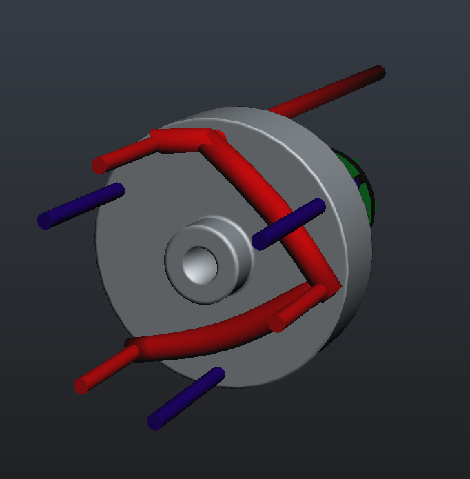
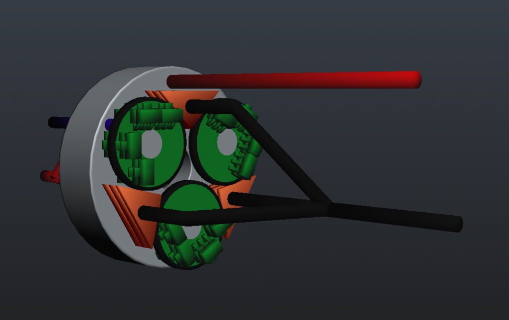
Massive image dump incoming!:
Sorry…but I’m pretty pleased with how this is coming together and it’s hard to show how it all works without a bunch of angles ![]()
The driver assembly is done!
Barring a few last bits of insulating heatshrink this element of the light is ready to roll :bigsmile:
-
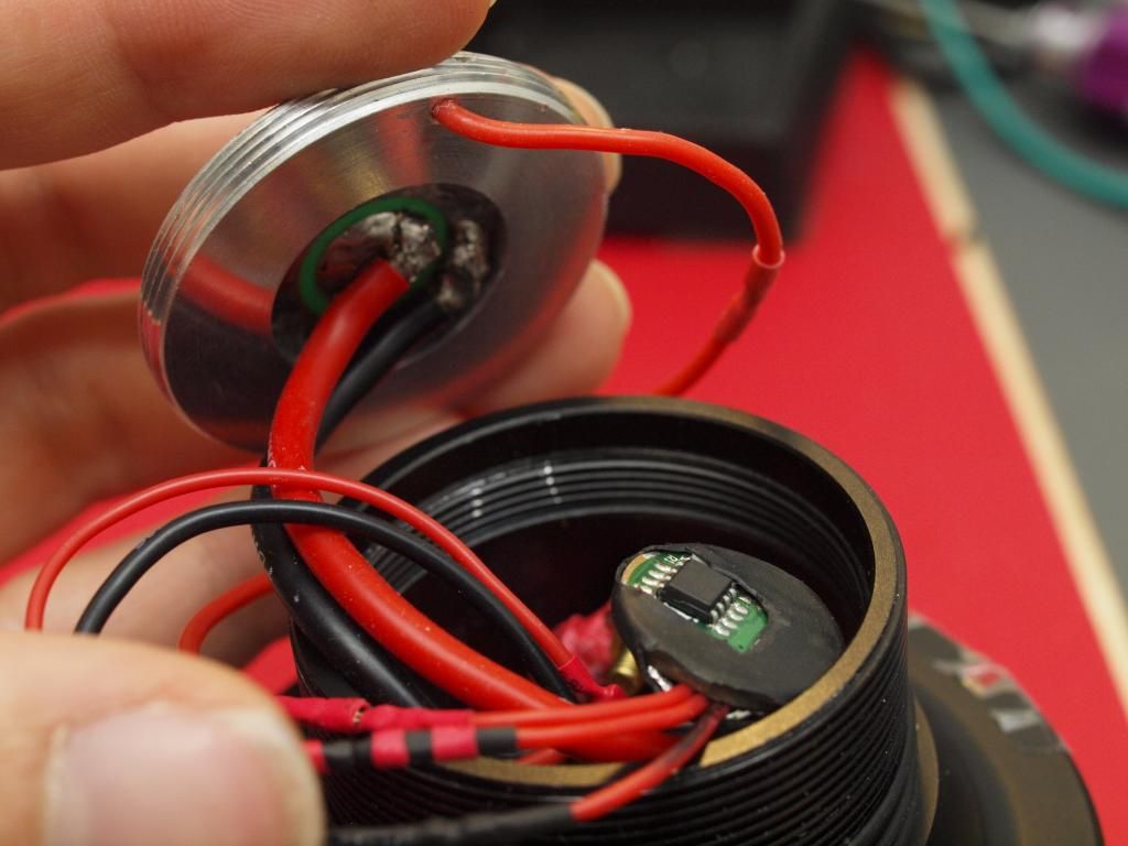
The MCU board is connected to the rest of the driver and the contact board by three detachable pin connectors.
Black is battery negative/ground, Red is batt positive switched by the clicky switch and Black/Red Stripe is the PWM signal going to the slave drivers.
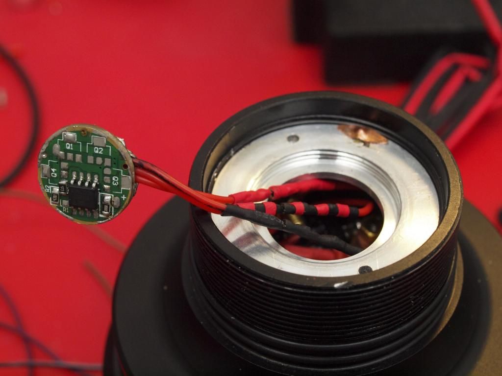
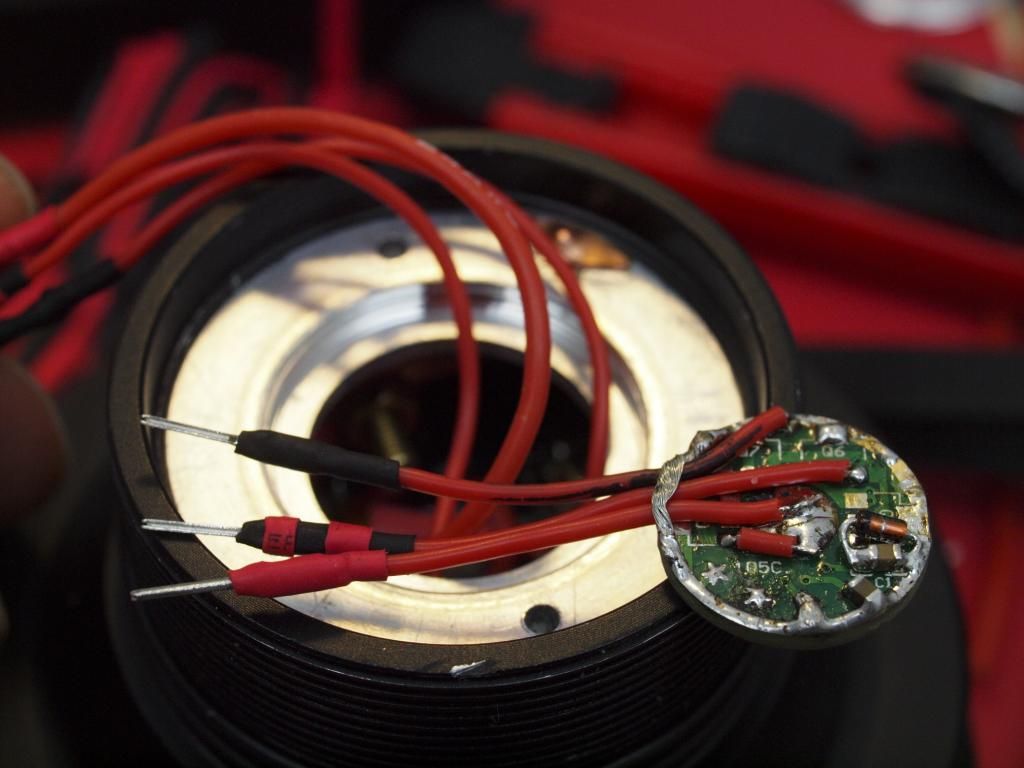
Contact board, MCU and wiring. Hmm will all this spaghetti really fit in that driver cavity??
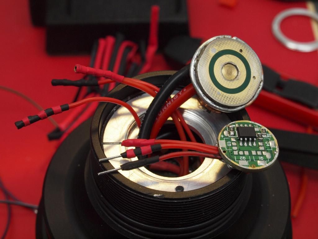
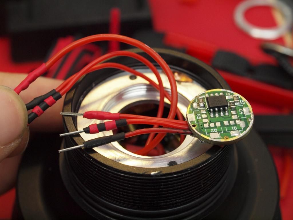
All of it should go together something like this. I need the extra length of main power cables to let the assembly twist down while tightening up the center contact board. It’s only a half turn or so at most but important that none of the cables are too short and get in the way. I also want to be able to undo and move the contact board out of the way enough to get access to the MCU later for reporgramming, more on that further down…
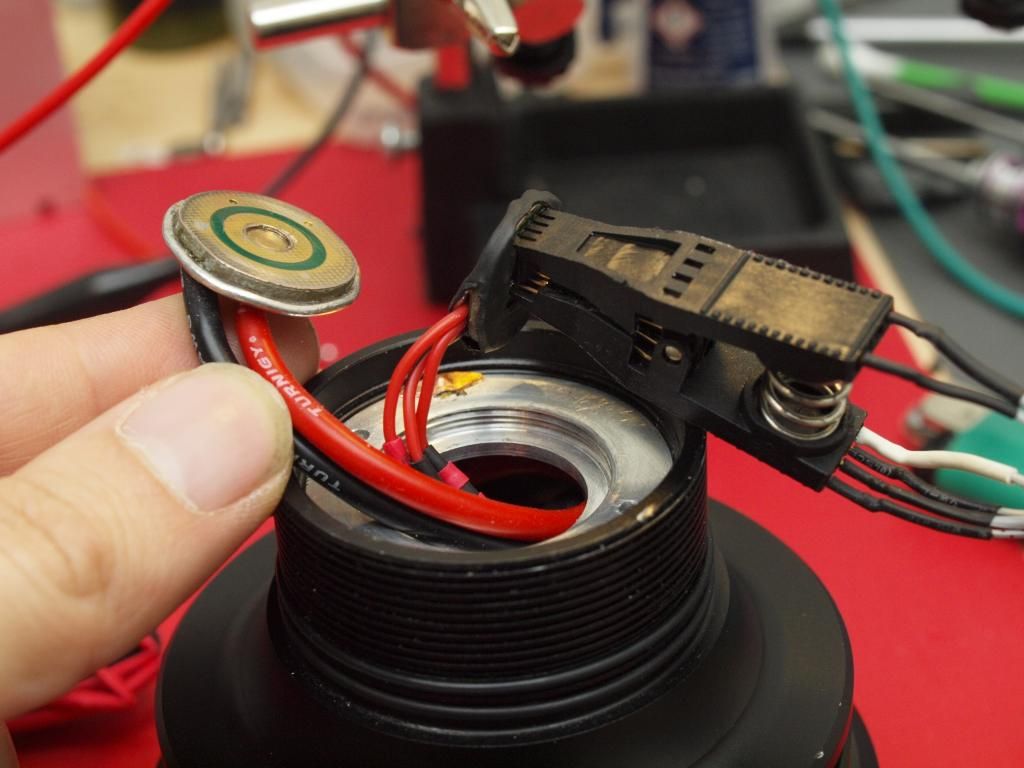
These are the main power cables coming from the contact board and the copper contacts that will get bolted to the driver assembly. Small black wire coming off this goes to the MCU ground connection.
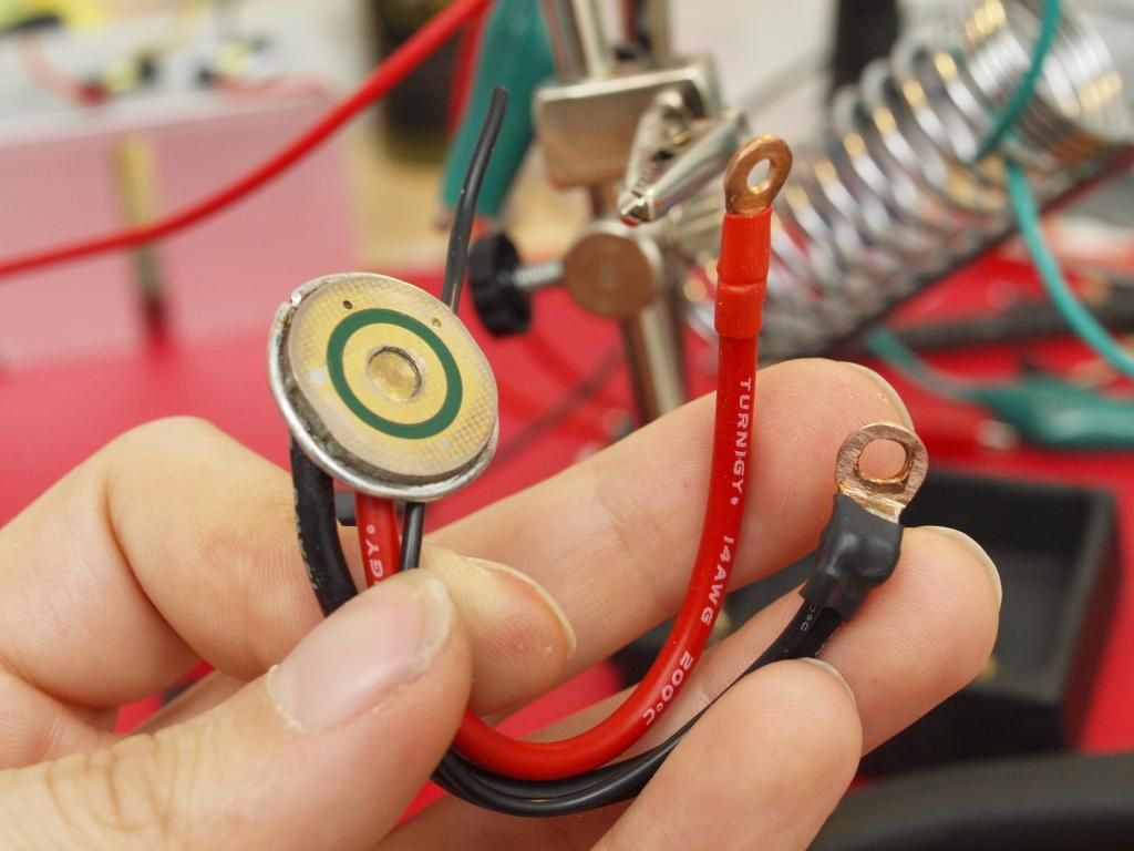
And this is how it connects up to the driver assembly. (Still need to properly insulate the positive connection before final assembly)
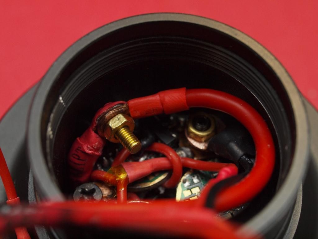
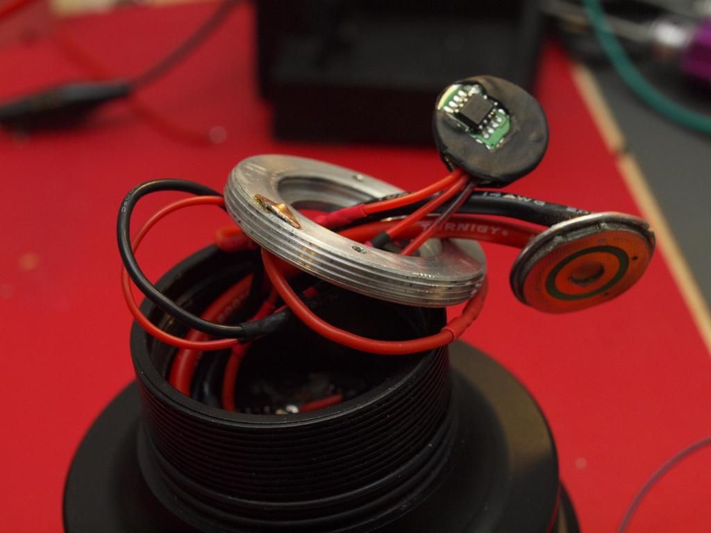
Here’s another angle showing the wire carrying the switched positive from the clicky switch through the aluminium contact board holder and to the MCU
Not much room to spare! ![]()
-
Just to prove it all works and goes together as it should, here’s a crappy gif showing the assembly process.
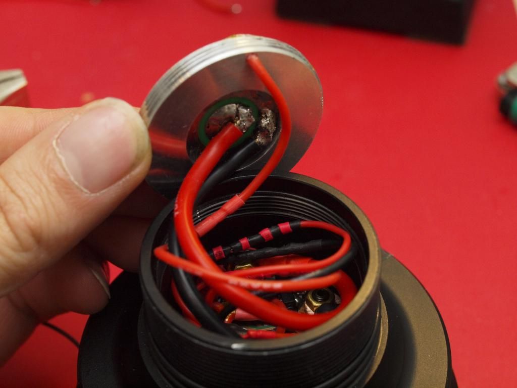
And again I want to be able to get to the MCU for easy reprogramming so here is what the in-light reprogramming process would look like.
it’s just a matter of unscrewing the contact board retaining ring, wrangling the power cables out of the way and fishing for the MCU board. ![]()
—
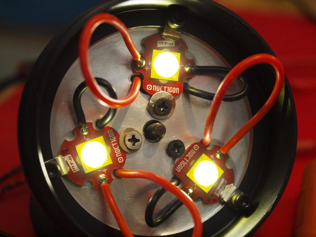
Job done!
Now…where did I put those Mt-G2s? ![]()
![]()
Orsm. RBD has your MTG-2 leds. They are with the reflector he last 18 months ago. 
I guess I’ve been away too long, who or what is an “RBD”?
And more importantly how do I go about liberating my MT-G2s from such a thing? They’re kind of important to this build…can’t be waiting another year to get this thing finished ![]()
Actually I wept slightly seeing the newest MT-G2 Q output bins on IO, mine seem rather antiquated in comparison.
Can I get this thing finished before the MT-G3 is announced? ![]()
RBD would be Rufusbduck. He lost from memory a reflector along time ago and its just stuck in my head for some reason so put two an two together rattled it around in my head for a Nano second and came to the above conclusion. I had the same problem when I built my shocker with the MTG-2 led being updated. I wont tell you what I ended up doing. As far as finishing before the MTG bazillion comes out will I suppose depend on how quick the mailman comes.
i cant wait to see it finished…
any new updates? JW if u gonna mass produce a few.
Aha yes of course, the master of looking so sternly at a piece of copper it cringes into an elaborate heatsink. ![]()
Well considering I haven’t even finished the first one, talking of mass production is a bit early methinks. Haha ![]()
But hey if someone is really serious about wanting a light like this and is realistic about how much it would cost for me to hand make them one. Then sure, I’d be up for building a couple more, why not.
Parts cost alone is over $300 last time I checked, so that should give you some idea.
Oh and Updates are there… I’m afraid you’ll have to look through the thread to see the latest stuff. I can’t update the first post anymore since the thread is so old… :~
I don’t plan on LED/MTG change or Driver change. Just the tactical handle and otterbox & rc batteries. I’ve already gotten a BTU-Shocker. So i thought it would be cheap (under 100). Also thinking of doing a shoulder mount like camcorder’s in the past. A u or clamp mount on an old shoulder pad camcorder pad.
Ah right so you’d be interested in a kit something along the lines of this?
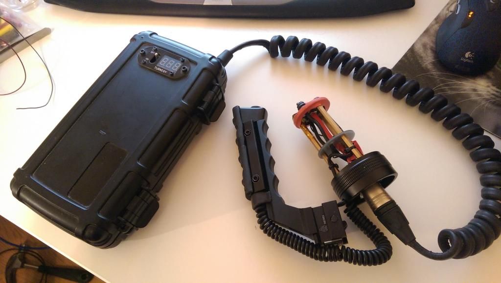
Yeah I could see that working but it does require a modified BTU tailcap or getting a run of custom tailcaps made up. And for the whole thing to thread straight onto a stock BTU, unlike on my light, the handle rail would have to be bolted to the tailcap instead. But in theory yeah that could work fine. A plug and play battery pack kit for BTU owners. ![]()
–2x 3S rc packs in parallel probably around 10,000mah (3s and much lower current requirements from stock BTU would allow for a thinner power cable)
-Main power switched by a Fet in battery carrier driven by clicky in trigger
-MCU in battery pack for automatic overcurrent/undervoltage protection cutoff etc. (still haven’t gotten around to adding this functionality to my pack either but should be relatively trivial)
But for under $100, I’m afraid not.
Quickly worked it out and the cost for just the parts in the image above is over $150!
I’m sure you could source things for a bit less but that’s what it works out for my build, big ticket items such as the battery packs alone will run you around ~60bucks.
yea that’s fine the only big problem would be finding another tailcap without buying the whole thing.
Yep definitely. I could send Ric at cnqualitygoods a mail and ask if he has any BTU tailcaps lying around unused. Maybe he can check down the back of a couch or something, who knows… ![]()
Vinh modded a few as well, might be worth PMing him too
I swear I did not clean Ric out of all his left over Shocker parts.
So you’re to blame! Hah, good thing I swiped them from you just in time then! They’ll be worth their weight in gold soon enough ![]()
Did he actually say those were the last bits he had laying around?
No I'm no sure. He did not have any lenses as I broke one and he had none left. He did send me some misc o'rings and a few other parts though I guess he had kicking around.
Internet broke so couldn’t upload any progress.
It’s alive! Finally ![]()
Running off the battery pack fully assembled for the first time was a really great moment.
But it’s already back in pieces, for final tweaking and assembly.
Measured 15Amp draw from a single partly charged pack and Lordi does it pump out the heat! I definitely need to spend some time maximizing the thermal path into the reflector and out to the front of the light because the BTU pill and body is completely overwhelmed by the heat these three emitters pump out. Not unexpected really and I’ll definitely have the turbo timer enabled on this light, probably set to 1.30-2min max but I’ll see how the thermal properties are when everything is fully assembled. Then I’ll find a medium/high mode power level that can allow for continuous operation and go from there for low.
Very pleased with the STAR off timer driver UI and Moonlight mode works great. I’m pleased with the output level set to 12, but I do notice a bit of the usual moon mode flickering. Wondering if the phase correct PWM leads to more stable moon modes at very low levels? Has anyone got any experience with this?
After running on high for 2 mins I also saw some output throttling/flickering even though the pill surface wasn’t above 50degs, so I need to make sure the 7135s aren’t getting too hot inside and throttling back. All told it’s a bit of a nuclear reactor this thing, especially since the battery pack doesn’t give in at all under these power requirements and just keeps feeding the juice! ![]()
Well as you can see still lots of tweaking and tuning to do but it’s getting there.
Oh and it’s quite a bright Mule this thing ![]()