Cree XHP70 up to 4022 Lumens and XHP50 up to 2546 lumens - Multi-die leds.

Nope, that’s not going to work for me!
Unless of course you seriously expect me to take my sunglasses off while walking the dogs at night?! Come on! :cowboy_hat_face: :~

:slight_smile:

But honestly I’m totally with you on this, I’ll take the nice, even tint of an Mt-g2 over a much higher output any day. Here’s hoping the Mt-g3 (if it’s ever released) will get closer to XHP kind of output while maintaining or improving the sensible array pattern and nicer tint properties.
It’s probably just me getting too picky, but I’m getting more and more impatient with emitters like the xml that exhibit really strong tint separation across the beam. It’s probably also one of the main reasons I like dedomed leds as they have a very even tint across the beam. Which, even if it is a ghastly shade of green at worst, your eyes have a much easier time adjusting to it because the light is one tint across the whole beam, not purple/blue in the spill and yellow/green in the hostpot as is often the case with stock XML/XML2s.

The beam color is different in several stages. And there are artifacts, X marks the spot, that are seemingly impossible to get rid of. I think an orange peel reflector would help a lot here.

I was wondering about that, it won’t help much in a single emitter light but in something like an SRK with 3 emitters.
How about taking care to rotate each emitter by a certain amount (30 degrees seems a logical starting point) and also having each emitter slightly (or heavily?) off center in their reflector. I wonder if a good combination of these two elements can help to “fill in the gaps” associated with multi die emitters. Seems to me the biggest issue with these emitters and the mt-g2 (to a lesser extent) is that the center of the cross, or darkest part of the emitter is exactly at the focal point of the reflector. Maybe there’s a way of nudging this center point far enough away to bring an illuminated part of the die more into play, then hopefully blend out any ringyness and inevitable artefacts across the three reflectors.
Just a thought.

I’ve been meaning to do a bit of software simulation stuff regarding this type of thing and it seems like a good opportunity to give it another go.

I found the colors to be more of a nuisance than the artifacts. A dim X in the middle of the hot spot isn’t so bad, with some distance you don’t even see it (the great white wall reveals all) but the color differences are always present.

One of the 4 dies had phosphor pulled off. I was de-doming it at 12A, had cut the circular part of the dome away from the substrate and that did come off clean, but that one silly die…

The die’s look exactly like 4 XM-L2 dies stuck in together, 2 have the wires on the same side, one on top, one on bottom. So the 2S2P shows pretty clearly in the bond wire layout.

Edit: Pretty sure it’d de-dome clean in gas. Definitely a tighter beam, the x is still there though, and the color ringing is worse.

Yeah for sure, dedoming seems to be the only decent fix for colour/tint variations. At least in my experience with XMLs, I’d imagine the same will apply to this emitter?
…hmm but with a dedomed XHP and a light minus green filter to get us back to a nicer tint, we’ve probably dumped all the extra lumens that we had over using an Mt-g2 in the first place… :zipper_mouth_face:

Edit: colour ringing worse after dedome? Wow that surprising, are you sure no phosphor was removed in the gasoline dedome
Edit: Edit: Sorry misread that, yeah I’d imagine gasoline is the way to go. No real chance of it going wrong as long as you’re patient, hopefully it’s not stuck on there more solidly than a standard XML/2

-

I did see three different colors in the one I tried. I didn't notice them after I took it outside. They seemed to blend out after about 10 yards. At 50 yards, it was just really bright white and had a huge spot, for a deep reflector. About 1.5 times the size of the MT-G2 spot in the same reflector, but I could still see a little of the black cross even at 50 yards. That's when I gave up on it. Small reflectors that are OP, heavy OP, would hide the cross quite a bit. It looks just like the MC-E and the old P7 leds and lots of them were put into lights. I think, if I remember right, to get rid of the cross, (well mostly get rid of it), the reflectors had to sit even with or just above the top of the substrate. I may be wrong about that, but of course, it would be the first time I was wrong.

I am willing to guess that in multi emmiter lights the cross will not show at all at any distance.

And I am willing to guess that in a OP-reflector of descent size (from C8 onwards) the cross will also be gone :-)

It’s a little off topic and I’ll post this stuff somewhere else once I do a bit more work on this.
Anyway, inspired by these new quad die emitters I started doing some reflector simulations with varying emitter die shapes and it’s starting to show some interesting stuff.

I modelled a mathematically correct paraboliod reflector of a generic depth (something proportioned like a c8 reflector). Dimensions are fairly irrelevant for this test since the die is also arbitrarily sized for now.
I simulated the die shape as the light source (no dome!) and traced the photons using a global illumination solution in mental ray. I wasn’t sure if the system was going to be accurate enough for these kind of tests (there’s lots of fudging and optimization going on), but with accuracy cranked to the max and a generous amount of simulated photons the results started showing some useful stuff.

-

Here’s the hotspot results with the emitter sitting bang on (as close as I can get) the focal plane of the reflector and projecting the hotspot onto a plane sitting more or less at infinity.


Circular Die (ie SBT-70) - Very clean hotspot! Just Lovely :slight_smile:


Square Die (ie XM-L) - This is what we’re all used to seeing. Note those distinctive petal shapes in the corona.


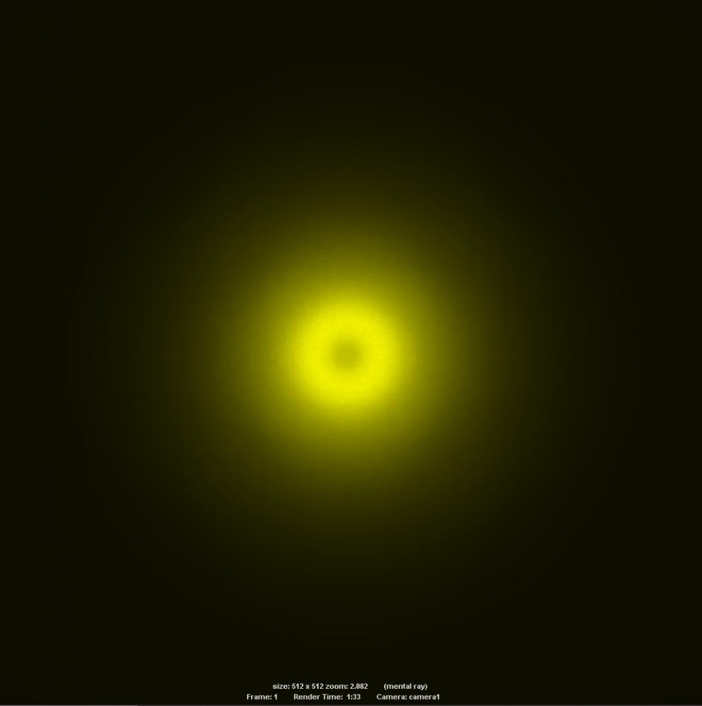
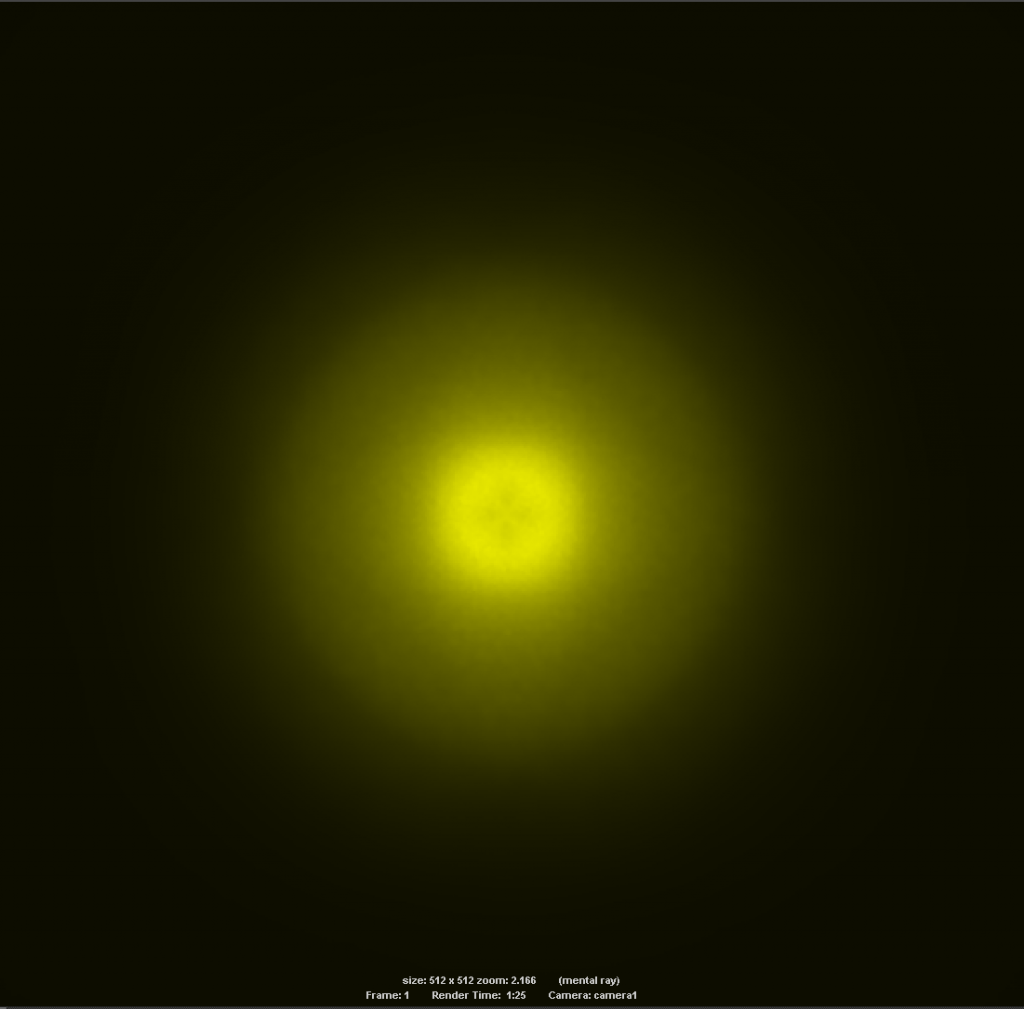
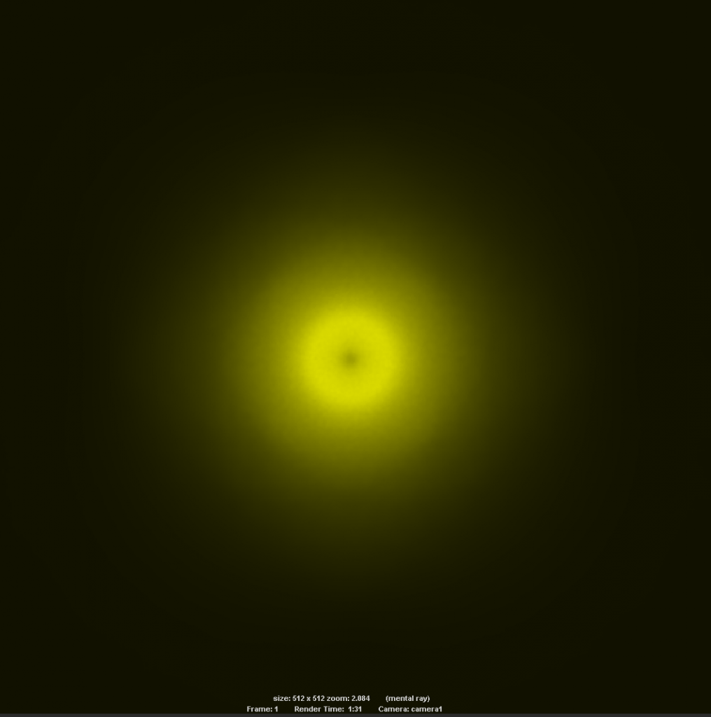
Quad Die (ie XHP-xx) - Very similar to square die but with a pronounced dark center, or donut.

So that’s an indication of the absolute best case scenario for projecting a die image from the focal point. Obviously for the square and circular dies this is a good target to achieve since it produces the most cleanly defined hotspot at large distance. For the quad-die however we may need to try a bit of fiddling! :wink:

-

Here’s what happens when the quad emitter is pushed deeper into the reflector, i.e by removing material from the back of the reflector, raising the emitter on a pedestal etc.
I figured pulling the emitter further out of the reflector would be a less desirable solution since that also reduces the amount of light that hits the reflector and as a result lowers output.

The increments are again an arbitrary unit, maybe about 0.5mm each time. If people find this useful I could do some more scientific tests with accurate measurements to try and find a sweep spot for this type of emitter.


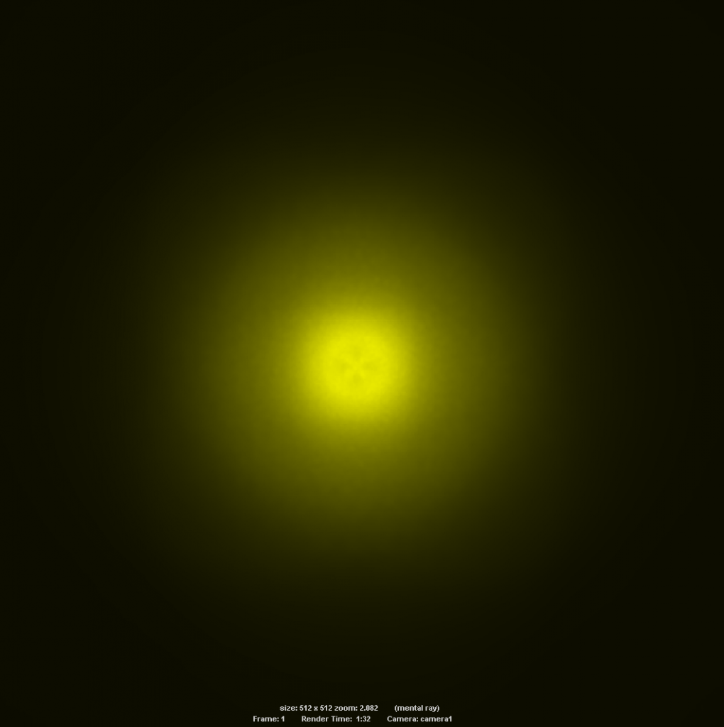
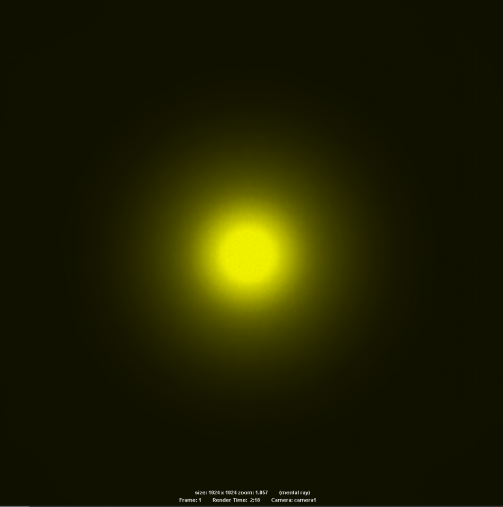
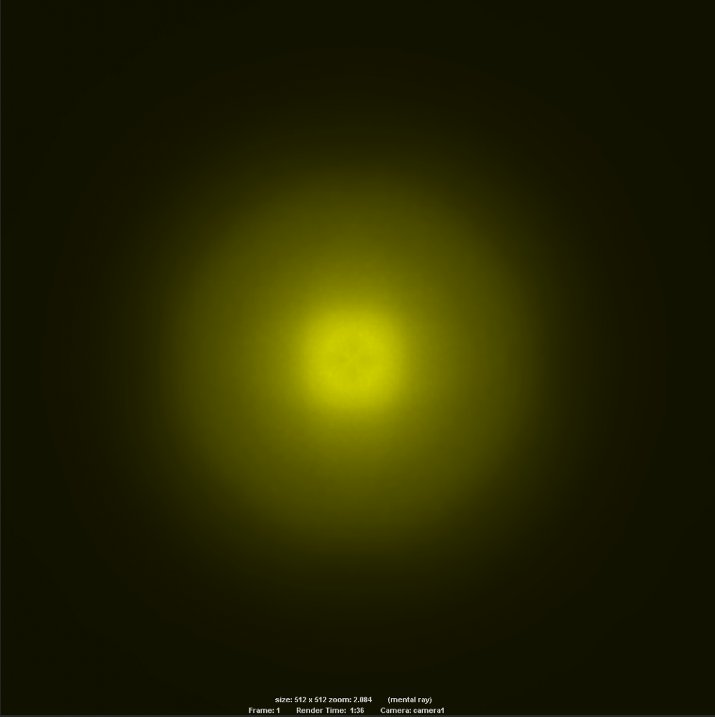
Emitter moved +5 units into the reflector. Center of hotspot looks better than before but the donut is still obvious.


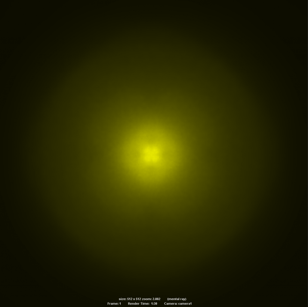
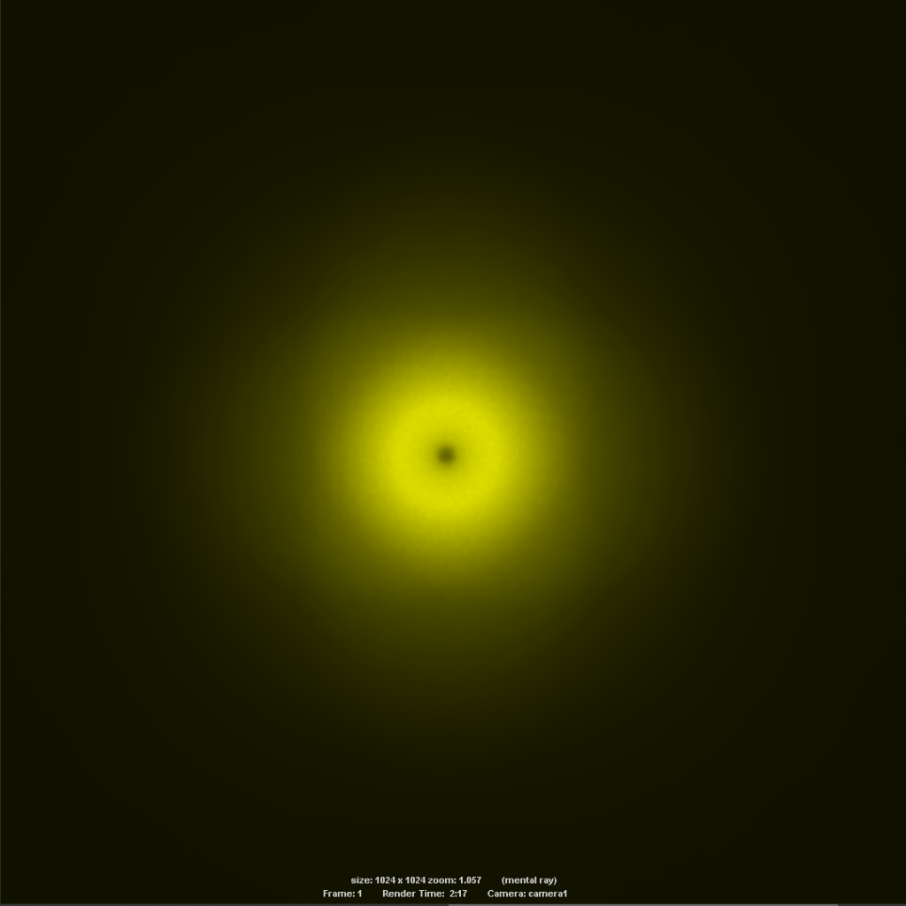
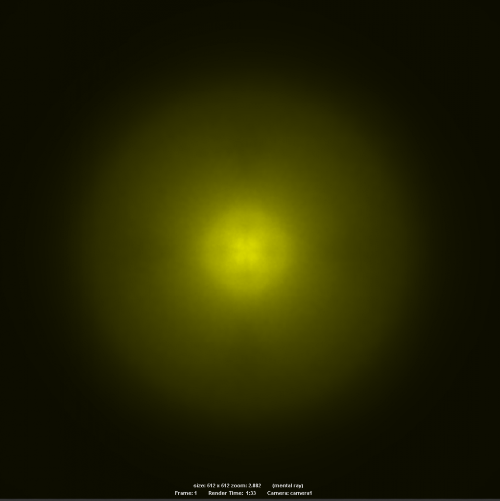
Emitter moved +10 - Note the appearance of the dim cross at the center. This seems like it may be the best compromise point, although the corona is rather large.


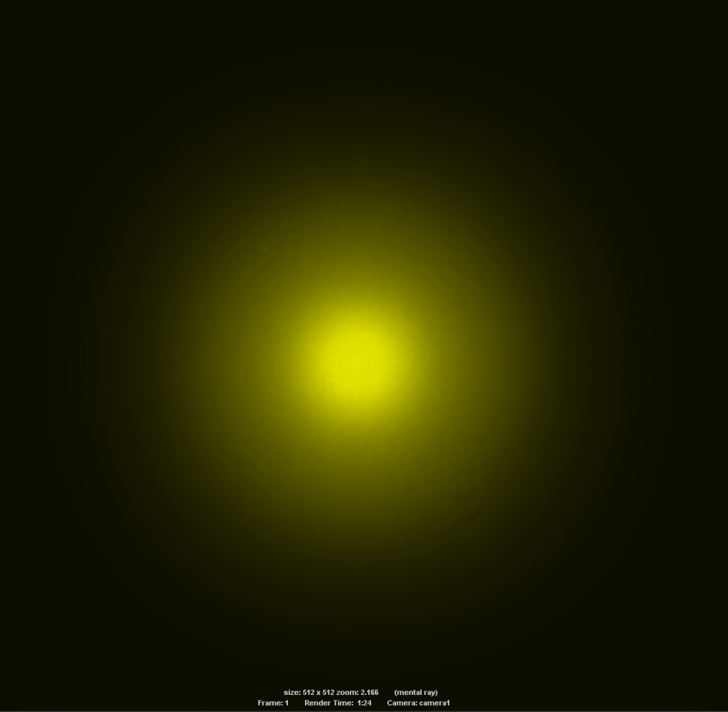
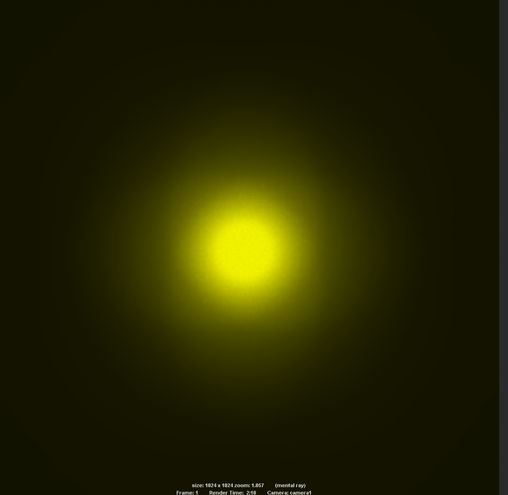
Emitter moved +15 - Really funky stuff starts to happen here! The hotspot suddenly got quite a bit more intense, and I had to tweak exposure of the render down. Don’t take this to mean that this setup is going to be best for throw, it may be something to do with those optimizations in the photon calculation I mentioned earlier.
It does seem to indicate a flip though, now the center of the hotspot is indeed the brightest part of the beam, maybe somewhere between the last two points is even better. More testing required.

-

So that’s what I’ve been playing with, I’ll do some more when I get a chance. It’s quite fun and I might be able to produce some handy animations or reference images that people can use to recognize when they’ve properly focused their custom led light. Or to recognize in which direction they need to tweak things if things aren’t looking right, I know when I was starting to play with led lights that this stuff was an incredibly frustrating aspect. Man those HD2010s used to annoy the crap out of me! :wink:

I will also do the triple reflector experiment for the XHP to see if combining off-center positioning with depth in the reflector in a certain way can eliminate the Quad-Die artefacts completely without resorting to an OP surface.
Maybe I’ll come up with something that works well enough to tempt me into buying a few of these beasties! 8)

LinusHofmann - Try lifting the reflector off the led. From the spot where you have it flush to begin with, lift it up instead of lowering it and see what you get.

Yep sure, I’m keen to see what the projected image looks like going the other way as well.
I intend to do a proper sweep in small increments from behind the reflector to in front, just figured I’d go forward first since there’s no loss of output going that way.

Edit:

Ok quickly did a set going the other way, this is pulling the emitter back out of the reflector in similar increments to before. Note that in these tests I don’t have a physical reflector hole in place to block the light as it would if you were doing this in a real light. That would obviously have some effect on the hotspot as well.

Things look very similar with subtle differences, so I put the positive adjustment equivalent image on the right for comparison


Emitter at 5 units Seems smoother overall but core is still decidedly donuty.


Emitter at 10 Definitely a softer corona on the left here, otherwise very similar (don’t read anything into comparative brightness, I can’t confirm this to be accurate yet!)

Emitter at 15 Again very similar here…

Getting to the point where you have the faint cross showing in the center of the hotspot (+10, –10), whether that’s further into the reflector or the other way may be about the best compromise you can get with this type of emitter.

Those are great simulations, love them!

When I have the XH-P70 in house I will have a go at some actual beamshots with various reflectors. OP-reflectors may do miracles for this emitter :-)

Yes I think with the right focus (i.e slightly out of focus, in the cross zone) and a bit of an OP it could look really nice. Of course the real thing is always going to behave differently to a sim (especially with the dome on) but I like having an empirical idea of what the physics are doing.

I actually assumed there would be a much bigger difference in the projected image between pushing the emitter into the reflector vs pulling it out, doesn’t seem to be the case here. Next I’ll add the reflector hole to the sim and see what that actually does to projected image.

I look forward to seeing some real world beamshots with various reflectors and see if the sims are true to life :slight_smile:

Faceted reflectors like the Boom from Ledil gave a flawless beam with quad dies.

It looks like they have one already for the XHP70 it won’t give much throw though

This is just showing us what we already know to be the case but your mention of the faceted reflector gave an idea to quickly simulate what the hotspot would look like projected through a lightly OP/Faceted reflector.


Both projections are with the emitter at +7.5 units into the reflector (in the dim cross sweet zone), one with a rough approximation of an OP surface and the other SMO.
Looks very promising indeed, especially since the same comparison done with the emitter in focus didn’t do much to eliminate the donut.

In other news, the sky is blue! :wink:

I’ve used this reflector in a couple of builds: http://cutter.com.au/proddetail.php?prod=cut1111

It works well with xml2 and mtg2, yes it is on the large-size, but it fits (with a bit of trimming) in a 109led head grafted onto a Mag.

I will ship one worldwide free to anyone who wants to test it with the xhp70 and post beamshots here.

That “approximation” of the smooth reflector looks almost exactly like what I saw with the Olight Triton reflector.

Nice work! And that Ledil reflector looks like the answer…

Do you have a link to a bigger datasheet showing the proper dimensions of that reflector? I can’t find one through google and that one on cutter needs to be studied under a microscope.

Cool, good to know the results are in line with the real thing.

Yeah, that drawing is unreadable on Cutter website!

The reflector is 50mm deep and 71mm in diameter. Overall it is 80mm in diameter.

It is made by Nata , but after a quick look on their site I have not found it….