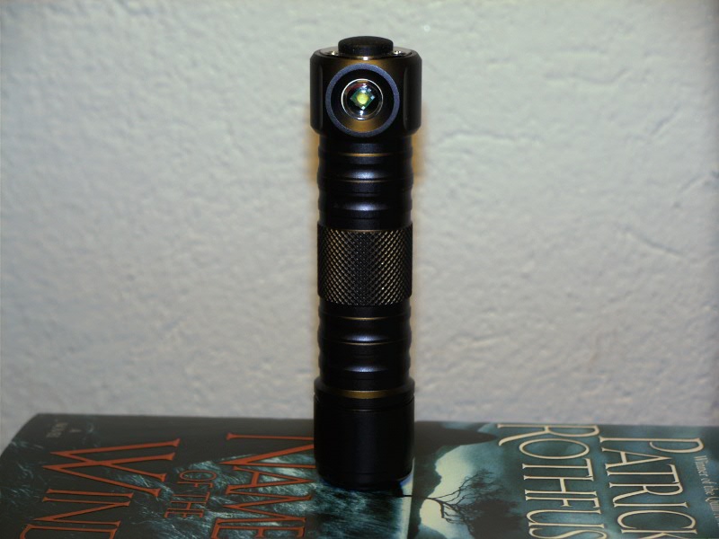
Some time ago I treated myself to the UF-H3B. When it arrived, I was really excited because I had been lusting after this for quite some time, but could never justify to myself the slightly non-budget price tag. Well, I finally held it in my hands, but when I turned it on, I was instantly disappointed by the ugly blueish tint. The annoying ramping UI didn't do anything to improve the impression, but the killer was the ridiculously low PWM frequency.
Something had to be done:
Next up was porting the BLF-VLD to the new hardware. This turned out to be a quite complex task, not only because of the new type of MCU, but also because of the different types of operation.
Anyway, the new driver has four modes in the main group, fully programmable from 18 modes available in the extended mode group. Ten of those are constant light levels, ranging from 1,4mA to 700mA. The rest are mostly useless disco modes and beacon or distress signals. I had to fill up the program flash with stuff 
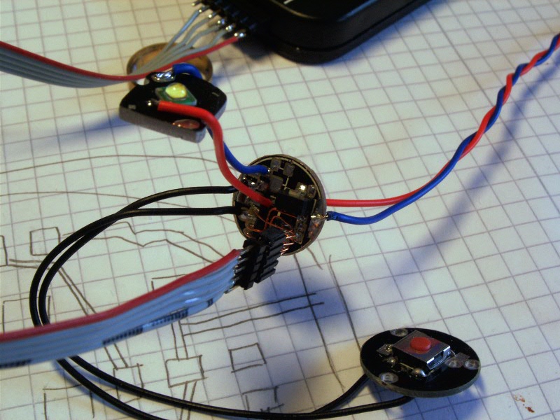
To make future re-programming easier (or even possible), I connected all pins needed to a five pin, 1.27mm pitch connector.
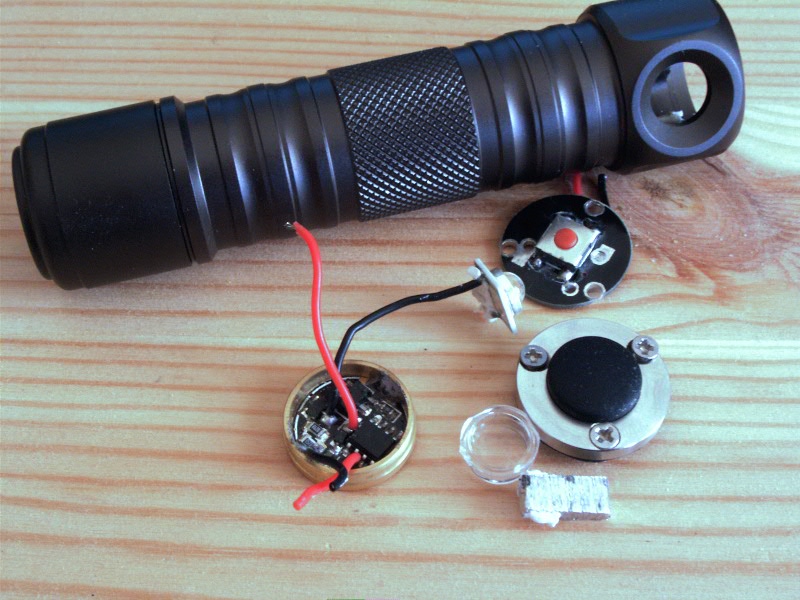
I also wanted to replace the XR-E with a neutral white XP-G R4. Unfortunately, the original LED was just wedged into place without any support PCB. This just wouldn't have worked with the smaller footprint of the XP-G, so I had to sand down a PCB until it fit into the light.
Next I had to glue everything into place. This is where things got messy:
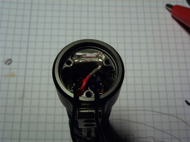
The plastic lens is glued to the body with Fujik silicone glue to make things waterproof. The LED's PCB is glued to the flashlight body with Arctic Silver thermal epoxy for improved heat transfer. On the right hand side, just below the screw hole, you might be able to make out the programming connector, fixed to the body with a standard epoxy glue. It's all pretty ugly, but it works.
So, here we are with a finally usable UF-H3B. It was a lot of work, but well worth it.