BTU Shocker Triple MT-G2 with a twist -- Aiming for >100Watt ~9000Lumens -- With external 2S power pack, handle etc...

Unfortunately not, that would certainly make testing easier. I do have an iCharger 1000w lipo charger that I could convince to supply a constant voltage/current (using the motor run-in mode). But I’d still need a powerful dc source to make that work, my best source taps out at 90w, unfortunately I left my 1300w converted 24v server PSU in Ireland. :frowning:

Hmm, although…thinking about that again I may be able to make it work if I power the iCharger off the Lipos and use it like a boost driver to supply a constant voltage to the light…need to see if it can safely supply 150w at only ~8v input though.
Don’t want to burn anything out on that thing if I can help it, I’ve had some bad experience with lipo chargers in the past going poof when pushed close to their limits in slightly unintended ways.

Edit: According to the manual the charger should be good for an output of 300w at an input voltage of 8v. So I think this is safe to try.
Will report back, hopefully with an output graph at various constant voltages! :slight_smile:

The GND springs are the more robust part of the interface because there are 3 and they’re all making good contact with both the aluminium contact plate as you say but also partially with the edge of the contact board which is directly soldered to the GND supply wire in the head. Everything is additionally clamped together and continuity is good on that I’m fairly certain.

The positive contact point on the other hand is a lone brass stud mating with the center of the 20mm contact board and a recessed second brass stud that’s soldered to the positive driver supply.
If there are losses it’s going to be here I’d say, it relies on pressure more than the others and the mating surface is a lot smaller. I just don’t have a great way of testing this interface with the light assembled as it currently is, wish I’d done this earlier.

I was contemplating doing away with the spring and brass stud on the positive and changing it out for a short beefy 6mm bullet connector. That would still allow the whole thing to turn but make more solid contact.

The bullet connector sounds good, but requires precision unless you soft-mount it somehow I think.

To keep the iCharger happier why not run it from a car battery? I guess it’s cold outside, but the car battery does seem ideal to me.

Yeah, although the battery carrier has quite a bit of give in it. It’s only hot glued into the bottom of the tailcap anyway so I think that shouldn’t be a problem. As long as things are relatively well lined up to begin with.

Coldness, heaviness and laziness all make that power source an unappealing prospect! :wink:
Although I should really have a LeadAcid on hand in future to stand in for this kind of thing.

I did just try using the Lipos to energize the Charger to power the BatteryPack to run the Flashlight though :stuck_out_tongue:

Works pretty good at full whack, only downside is I can only adjust the output voltage by 0.1v increments but otherwise it’s perfect. CC and CV at >150watts, plus a soft ramp up to avoid things going bang too quickly! Not too shabby at all. :smiley:

Let’s see if I can figure out what’s going on a bit better like this.
Thanks for the kick to rethink this. :slight_smile:

Nice! I wish my hobby charger had a motor drive mode… it’s been standard on “nice” chargers for so long I just assumed that the wave of modern, cheap, character LCD controlled chargers all had it. My 200W cheap thing from HobbyKing taught me differently: I assumed wrong. I’d have chosen a different charger at the time if I’d known that feature wasn’t present on the lowest end units.

Can’t wait to hear the results.

Yeah, it’s certainly something I’ll be looking out for when choosing chargers in future. I’d always dealt with brushless motors in rc helis so never saw the need for it’s intended purpose but as a variable CC/CV power supply of up to 1000w it’s bloody useful!

Ok, anyone still awake in here?

Time to wake up cause I have more Graphs! Yay, exciting! :nerd_face: :party:

Spent most of the day/evening rigging up and running tests using the new iCharger based stable voltage supply. It was almost a complete success, giving me a much better idea what my voltage overhead was doing and just how this driver behaves in and out of regulation. But particularly interesting was how the 7135s behave when I assume they are just on the cusp of being in and out of regulation. Things get pretty freaky there!

-

Unfortunately the one failure of the tests was to get an accurate value of what the vBatt voltage was. I know exactly what voltage the iCharger is putting out (verified and precise compared to the digital readout) but since the leads running from the iCharger to the battery pack connectors where relatively long and passing through my Turnigy power meter (as a backup current reading) I had to measure the actual voltage arriving at the battery pack off one of the deans ultra connectors using my DMM. No problem right?

Well so I thought but after doing 3 tests and seeing a consistent voltage drop (seemed rather large tbh), I touched the probe leads leading to the DMM with my hands and this consistently threw the reading off by as much as 0.3v. I checked all my connectors, resoldered aligator clips, swore at the crappiness of my DMM… tried another DMM (also a fairly cheap one) but I kept seeing the same thing, it seemed if I was touching the DMM or the leads in any way the readings would jump up 0.3v and give what seemed to me a more precise measurement. But leaving the DMM to do it’s thing it dropped way down again.

So I don’t know what’s going on, my theory is that the iCharger is not putting out a particularly clean voltage and that the buzz on that line is throwing off the DMMs, maybe my touching the circuit produces a slightly different waveform and a different voltage reading as a result. I dunno, it was really frustrating and I don’t have a scope to try and check anything high frequency related.
Anyway for now I don’t know how much voltage I’m actually feeding into the deans connectors at the battery pack but simply going by the iCharger voltages it already gives a pretty interesting look at the driver behaviour.


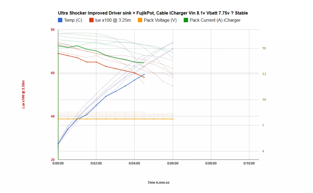
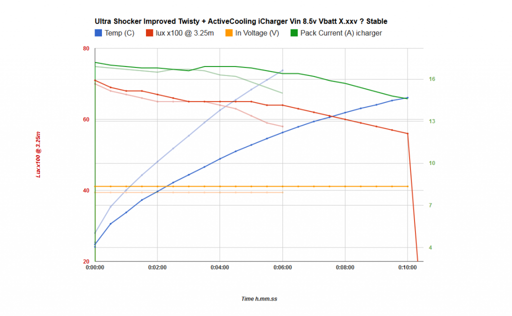
Let’s start with a low regulated voltage of 8.1, I was measuring 7.75v at the battery pack but as mentioned above, I can’t trust this reading. I suspect this may be closer to 8v at the pack.
Either way, this is not a good output graph, current is way below the regulation target of 17.5A, starts at 16.3A and output drops with temperature increase. Remember this is with no voltage sag in the supply at all! This test also ends early because my lipos powering the iCharger ran out before the 6 minute mark, too tired to run it again tonight. :stuck_out_tongue:


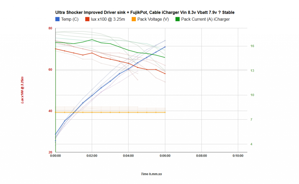
This one is at 8.3v on the iCharger. Funky stuff happens to the current here as the driver/light warms up, starting around 16.5A again it now peaks strangely to almost 17A at the 2 minute mark. I noted plenty of flicker on the troublesome emitter/driver during these tests as well.


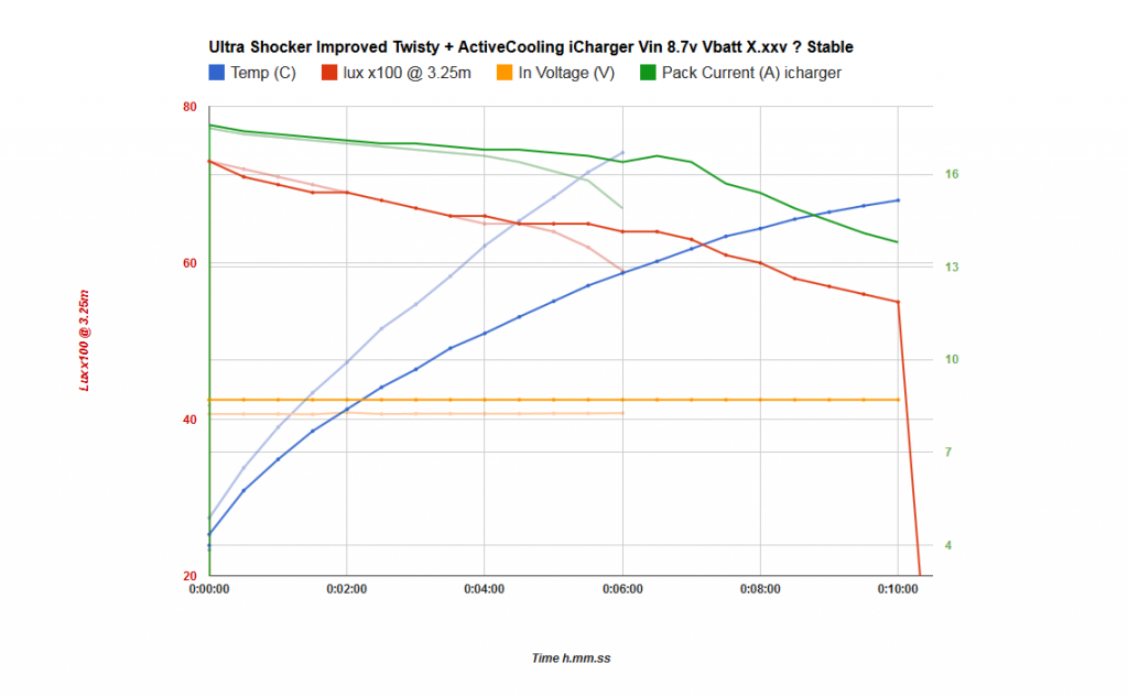
At 8.5v the current graph is looking rather similar to the no cable tests I ran earlier on. Still only starting out at 17A but relatively well regulated from there on. Steady decline at start and with that little bump at the 2.5-3 minute mark. Less flicker noted and actual output is maintained really well here, we’re still well above 60klux at the 6 minute mark which is great!


Well praise the lord does that look like a hint of regulation there?? I can’t believe my eyes, at 8.7v the current curve is very very clean. Not flat but this is more like what I expected to see. No funny business from the output side either and I’m almost certain I didn’t notice any flicker at all during this entire run. Of course because the drivers are now burning off more energy and also maintaining a higher output the heat cliff is very noticeable at the end of this run.
I still get the impression looking at this graph that the light is happiest running at this kind of voltage overhead, whatever that ends up being.


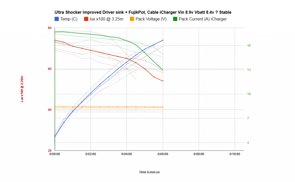
Now we’re starting to push it a bit, 8.9v shows a more extreme version of the previous test. But this is still the nice predictable shape to the curves that I was hoping for, the heatcliff is arriving earlier just as expected and output tracks identical to the previous test despite the higher drive current. I suspect that’s simply the emitters hitting a bit of a limit in terms of how much heat it can shift into the pill. Output beyond the 8.5v test seems to be determined more by the heatsink temp than the drive current.


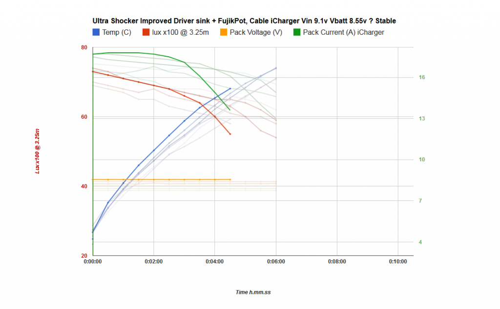
And finally the extreme torture test at 9.1v. Things don’t stay cool for long at this input voltage, the driver seems to peak at 17.8A (~0.3A higher than it should based on the number of 7135s i used, but hey up to now all I’ve seen is driver current missing the target in the other direction so I’ll take it…) then it drops as temps get critical. Output settles into it’s steady decline, identical in slope to the previous 3 tests and then follows suit over the cliff. This test was ended by one of those alarming mega flickers so I hope things are still ok in there :stuck_out_tongue:


So that’s about it for now, it was a massive pain in the ass doing these runs. Waiting for the light to cool down to 24 degrees after each one and recharging my lipos in between every couple of runs. But I’m pleased with the insight it’s given me, once I figure out what my actual voltage drop is before the battery pack I’ll have an even better idea of what’s going on.
Plus it’s given me a really nice baseline that I can compared against when I go resistance hunting! :slight_smile:

Ultimately I think I’m losing closer to 1.5v across all the connections and cables before we get to the driver, much more than the ~800mv I was hoping for.
But that’s just a gut feeling based on these tests and seeing where the regulation actually seems to start happening, I’ll know more when I have precise vBatt measurements to look at as well.

Thoughts really welcome, does this look familiar to those who know these 7135s better than I do? To me they seem to be doing really funky stuff that I never considered before, especially in the range where they are presumably just switching in and out of regulation. I also thought their behaviour would get MORE erratic as the voltage overhead and temperatures increased but frankly they seem to run much more predictably in those conditions…I’m a bit lost tbh!
Haha bring on the linear FET drivers! :stuck_out_tongue:

Cheers
Linus

Good work there.

RE: the flickering… My money is still on the emitter, but I’m not one of the experienced gurus. I figured I’d hold my tongue when you said the problem had gone way: no reason to be a downer.

I noticed one thing while doing a brief test with a small number of 7135s (less than 8 ). The more I added - the higher the dropout voltage. I am unable to explain this behavior, to me it is not logical.

Ah no the warm up flicker on high hasn’t ever gone away, except seemingly during the higher voltage tests I just ran. Sorry it was the flicker on moon mode that had fixed itself. I have my fair share of flickers here :stuck_out_tongue:

No that doesn’t make much sense does it. Could explain why I’m seeing such a high drop, provided it’s not caused somewhere else in the power train.
Were you running them off an MCU perhaps at the time? I wonder if it’s possible that the PWM pin on the MCU struggles to fully turn them all on, surely with 48 of the buggers switching them all is a fair task. Could that be it?
In my case I’m also using a fair distance of thin wire to connect PWM pin to the Vcc pins, not terribly long but certainly a bigger distance than the average board trace on a 17mm driver. Combine that with the relatively low 4.3v zener voltage source I wonder if that isn’t contributing to the weird behaviour and high voltage dropout I’m seeing.

I may try bypassing the MCU board entirely and simply driving the Vcc pins directly off a 6v dc source. Just to eliminate any possibility of only partially turned on fet switches in the 7135s.

Ah, I see. (RE: the flickers)

Sorry to make observations which do not make a lot of sense. Sometimes mentioning crazy stuff is poisonous information: everyone starts seeing the same false thing. Hopefully we can avoid that and get to the bottom of things with enough measurements. I hope to re-attack testing for that problem myself.

I do not recall what I was using to turn on the 7135(s) for that test. I would say that your suggestion is a good one (giving them 6v directly). The required Vdd is quite low according to the ADDtek datasheet: 2.7v.

Another thing of note in the datasheet, check out the OUT CURRENT vs. OUT_DROPOUT VOLTAGE graph. It shows an odd blip upwards right as dropout is hit. Maybe this explains your odd performance around 8.3v w/ the iCharger.

EDIT: the datasheet also claims 200uA of supply current consumption… so 48x would be <10mA, which should be no problem for the ATtiny’s output pins. I don’t know what speed they can switch that load at though, capacitance is also not mentioned by I assume it’s incredibly low.

great work Linus!

thanks for sharing. :beer:

Truly amazing! I applaud you for all your efforts!

Yes very interesting, that could well explain some of the weird behaviour. Also I may be missing something but it doesn’t state at what temperature that test was done, but I’d assume that’s done in ideal conditions showing a best case scenario.
What I’d love to see in the datasheet is more graphs based on temperature, since there’s no mention anywhere about the throttling back behavior we observe when temperatures get too high.

Surely if that was an active control system to protect the chip they’d mention it in the datasheet? More likely it’s simply a side effect of the circuitry not working right at high temperatures right?
Makes me wonder what else is happening inside the chip on the way up to those high temperatures… :stuck_out_tongue:

Dropout voltage graphed against out-current like it is in the datasheet but done at various temperatures would be very interesting. I suspect it can vary a fair bit as the chip heats up.
Could temperature have been a factor in your dropout observations do you think? More chips, more amps, more temperature and a higher dropout as a result?

They strongly advise keeping operating temperature below 85 degrees (max junction temp is given as 150) but I’d love to see how higher temps affect dropout voltage and max out current directly.
Only one way to find out I guess! :wink:

-

“What is AMC hiding! It’s all a conspiracy, I have seen the light…stop using 7135s you brainwashed sheeple, it’s all a big cover up. Wake up!” :open_mouth:

We really need a tinfoil hat emote… :slight_smile:

I don’t think so. As I said, it was <8 chips. I was operating them on a pair of those 4x7135 PCBs I think (in free air). I will re-test. Maybe I have stripboard that the 7135s will fit on nicely.

Cool I look forward to seeing your results on that.

I’m not sure I have the right equipment to really test this stuff accurately, but I’ll have a go at characterizing the thermal behaviour. Maybe something like soldering a few 7135s to a block of copper and heating the copper to various stable temperatures to see how that affects their regulated output and dropout behavior. I don’t want to rely on just letting the little buggers heat themselves up from their own junction temperature but see how they respond once heatsoak has set in.

From my testing in the light it seems heat is always a factor in how the chips perform. Even when out of regulation completely the output current seems to drop linearly as things get hotter. Wonder if I can replicate that in an isolated test.

Probably so. I think sense resistors are actually characterized in their datasheets RE: how much the value changes with temp.

Yeah, right! Seems strange not to include something like that in a datasheet for a device that’s almost invariably going to get really hot, just by it’s nature of being a linear controller.

The blower fan I ordered a while ago finally arrived today, so I sellotaped it to the light and re-ran a couple tests to see how things stack up with active cooling.

The plan was to direct all of the airflow from the blower over the majority of the meager heatsink fins available on the BTU. I just did this with electrical tape for now, keeping the airflow contained and running between the fins top and bottom then leaving through an exhaust port on the opposite side.

The fan is designed for 12v so it doesn’t quite run as fast as I’d hoped, but it still shifts some decent air and makes quite a racket on 8v. :stuck_out_tongue:
Ultimately I think I’ll mount the blower flush on the side of the battery tube and fashion some kind of a 90degree duct to redirect the airflow through the fins. All mounted on a removable modular picatinny rail setup of course. Maybe even make it temperature controlled if I can be bothered. :slight_smile:

The following graphs are simple reruns with the blower on full compared against the previous tests. Most obvious difference is I could easilly run the test to 10mins before getting worried about heatsking temps exceeding 70degrees.

Nothing too surprising here, although I was hoping to see some plateauing of the temperature at some point, guess I need two fans after all. :stuck_out_tongue:
It’ll probably keep up better when the light is running off batteries.

Also of note is that a much lower heatsink temperature seems to only really affect the drivers, ie by delaying the heat related behaviour where they drop output current. The leds don’t seem to produce noticeably higher output at these lower temperatures and are primarily handicapped by the drivers throttling back drive current.

Although granted I don’t trust my light meter readings between tests enough to show subtle differences in output regarding temperatures at the leds. Sometimes it can be as much as 5klux out at turn on and when I compensate the graphs to match performance at the same drive current draw they line up perfectly again.
I’d need a decent integrating sphere to really see what differences in output actually are.

I also decided to go resitance hunting and started by reinforcing the twisty interface contacts a bit. Just for peace of mind and to see if I could gain any noticeable voltage overhead there. The contact pressure had declined slowly since I made the thing and that was bugging me, it was nice and tight to begin with but with all the testing and reopening/closing and general wear it wasn’t quite as reassuringly tight as it was. The springs where still springy but the tolerances had just opened up some in general.
The positive path also needed a bit of beefing up and improving to put my mind at ease :slight_smile:

I added an small disk of copper to the top of the positive brass post to increase the height a bit, then ran an additional length of 16awg wire through a hole in the carrier disk and soldered it directly it to the thick positive wire coming from the connector. I also jammed some spare silicone tubing under the spring to ensure contact pressure was really high for a solid connection.

The negative posts were also overhauled a bit and I replaced copper braid in two springs (which had started failing) with 18awg wires. These should make good contact.
Ultimately as a result of all this I almost couldn’t tighten down the battery tube, the contact pressure and friction was considerably higher than before…and the positive post showed a nice polished arc where it mated with the brass recess on the contact board! Great

I ran tests at 8.5 and 8.7v after all this and compared against the before graphs, that showed no noticeable improvements at all…nothing! The bumps and dips on the current readings all lined up and so did everything else, so little difference in fact I won’t even bother posting the graphs.
A bit disappointing but I think it’s safe to say the contacts where likely good enough to begin with and I can at least rule this out as a major resistance bottleneck in the light.

Finally just a couple shots of the whole light after a hard day strapped into the test apparatus. 8)
Shows how it sits in the hand as well. It’s really a very comfy grip once you get used to the unnatural weight of the thing :wink:

Urgh, I’ve been playing in my 3d sandbox again…and that usually means new things need to be ordered from china very soon! :wink:

This time I wanted to cook up a functional, decent looking and completely removable blower module.

Here’s the result using various random bits of metal and plastic (see if you can spot the other half of the AC plug pack case that I also used to make the trigger housing… no waste here! :wink: ) and a nice black aluminum lens hood to act as a duct to contain and direct the airflow across the pill section.


The duct covers the entire surface of the pill and should offer some nice options for directing the airflow. Maybe it will work well enough in this configuration, with the air going around a bit before blowing out through the gap between the heatsink fins and the back lip of the hood. Could have part of the exhaust area blocked off to control the flow better… or I could seal off the hood all the way around and drill some exhaust vent slots/holes on the opposite side to the blower. Not sure yet.

Everything is picatinny rail mounted of course for easy removal. Power will be provided by a socket on the tailcap and the usual spiral cable to make the connection. There’s also plenty of room inside the improvised elbow joint to house some electronics to control the fan. I envisage a basic control pot sticking up the top of the assembly at the elbow for starters.

And of course you’ll notice the shorty configuration of the light has made a comeback.
I think I have a good way of making this configuration work now so when my spare BTU parts finally arrive via the rusty bucket express I’ll give it a go. :slight_smile:


This quick image slap-up shows the shorty look on the real thing. This one’s actually a bit too short but you get the idea, it’s much more compact and quite a lot lighter.

-

Btw if you’re a bit insane like me, have a BTU shocker gathering dust and fancies the look of what’s going on here. I’m contemplating building a few more of these lights (hopefully much improved upon this prototype) over the next couple of months.

I’m having a lot of fun building and testing this thing but there’s only so much money/time I can justify spending on it. Unfortunately having built this one I see so many ways of improving upon it should I build another. If I can build a few lights for other people I have an excellent excuse to keep tinkering with this thing! :bigsmile:

Here’s a quick breakdown of what I’d try to do for a V2.0 of this light. (Copied from a PM I sent to another member)

-Shorty Body configuration like above but with power indicator led built into trigger switch housing. Same reverse clicky with off-time driver UI, my personal favorite combo atm.

–9000mah 3s LiFePO4 9.9v battery pack (LiFePO4 chemistry for the better suited voltage overhead and stable discharge performance) Plus constant >9v availability for a VERY wicked DD mode. XLRs will probably be replaced with Speakon high power connectors to handle DD turbo currents. Also twin power relays in pack will be replaced by power mosfets for smaller resistance loses and lower power consumption.
The pack will also have a nice new display on the outside showing pack voltage and current draw. Otherwise the same as prototype.

-Drivers based on Wights Linear 7136 Driver with DD turbo.
Modes: High, Med Low etc tuned to users preferences and stable long run performance. Driver running off-time STAR firmware modified to handle the DD bypass.
Turbo: With the extra LiFePO4 voltage on tap I can easily see maxed out Mt-g2s on DD. Over 12Amps per emitter for short bursts (heat limited short runs of course but >12,000lumens @ ~300watts should be possible). That’s also not just on a fresh charge but you’ll have a very impressive turbo up your sleeve basically all the time until the battery is dead! (this is a rough idea, the drivers and packs need to be tested to see precisely how they behave…but I’m certain this power source and driver combination (provided the driver tests ok) is going to be a better way to go than my 7135s and 2s lipos).

-Active external cooling module as shown above. If I can figure out a nice way of having it temperature controlled I will. Otherwise a pot to dial in fan speed. (Note: The light in general won’t be particularly water proof but this part will certainly not hold up to getting wet!) This cooling system also won’t be able to keep up with turbo mode temps (nothing much would beyond a dunk in an icy lake!) but it will certainly help with the cooling down periods between blasts! Which to me is frankly almost as important. And of course it will enable longer stable running on the “lower” modes.

-Improved heatsinking mass behind driver cavity. Given the new driver approach I should have a bit more space to work with to improve the thermal paths for both the led shelf and the driver mosfets themselves.

So shoot me a PM if you’re at all interested and we can discuss things. Warning: parts cost alone is close to 450dollars so the term “budget” doesn’t really apply here. :wink:

Cheers
Linus

:beer:

you are :open_mouth:

I pretty closely skimmed your post (gtg for now!). I’ll come back and read it at a more leisurely pace soon.

In the meantime I wanted to say this: why are you looking at an external blower? It seems to me that integrating a blower inside the unused space of the battery tube makes the most sense. The concept of being able to convert back to a fully-handheld/no-external-batteries light seems like nonsense to me. This a seriously powerful build and will require a remote battery pack to be useful/interesting. You may as well treat it that way and install a blower internally.

There’s plenty of space in there. Here’s how I think it could go down (but I don’t own a BTU Shocker): If you modify how power goes through the head and into the battery tube & minimize driver size you’ll have enough room to drill/cut vents at the bottom of the fins. After that you route the power wires as far off to one side as possible (top side, towards the handle). Use a small blower with the intake facing the front of the light, then seal the tube around/behind it. Vent radially around the blower. You’ll only be able to fit maybe a 30-35mm blower in there, but I suspect that would make a big difference. You could also look at using an axial fan with a high static pressure in the same configuration.

That’s all my two cents and it’s not my build of course… it’s your show! I just noticed that you hadn’t mentioned considering this option and kind of wondered why.

Is an intercooler being incorporated with the turbo blower? If so this would greatly increase the density in the battery increasing efficiency and greater lumen output.