BTU Shocker Triple MT-G2 with a twist -- Aiming for >100Watt ~9000Lumens -- With external 2S power pack, handle etc...

As far as I know, PWM at 255 is never truly 100% on, only very close to it. And the ATTiny13as are definitely sensitive to temperatures, I used that for my temperature monitoring experiments, but I wouldn’t know how that has an affect in this case.

For my own triple MT-G2 I’m designing a new driver that will use all outputs on the MCU to use as simple ON/OFF to trigger chains of 7135s. Using four chains of 7135s will give a total of 15 selectable modes without PWM. I started looking at MOSFETs and all that and it didn’t take very long to realize it’s beyond me, so I’m just sticking with what I currently know how to use.

That’s interesting, something I’ll definitely be scoping out soon enough. I heard a while ago that the (I think) KD7135 or early Nanjg based boards had a firmware bug that ment they weren’t truly doing 255 at max output. So you’re saying even on something like the STAR firmware the output isn’t solid. Maybe this is what is getting worse and causing all the weirdness as the load on the PWM pin is increased.

You haven’t noticed any flicker at all on your triple mt-g2 as it warms up? Some comparative measurements from a similar light would be really interesting to see.

So you’re saying there’s a difference in output stability between an Attiny pin configured for PWM (even if the PWM is pegged at 255) and a pin set to constant ON output?
Edit: If this the case would it be possible to do a moonlight-special type of thing and just switch on a second output pin (for 100% mode) wired in parallel to the Vcc input of all the 7135s. Share the load between the two and reduce instability in the waveform?

I really don’t understand these little buggers enough. So much to learn :stuck_out_tongue:

I read your PWMless driver thread, but did you notice any unwanted behavior from the PWM-ed 7135s in your light (at 100%) that led you to making this design decision? Or was it simply about gaining efficiency at lower modes?

Can’t say I’m sure about it, wight’s comments on this will be far more valuable. From my understanding PWM 255 still is switching, not constant on. This switching may or may not be affected by high temperates.

I haven’t noticed any flickering at all on high modes. It does seem to flicker a little when I run really low PWM values, but other than that no flickering at all. But I have not run it for longer than the 1:40 hot potato test. I won’t need to in real life use. However, I haven’t looked straight into it though. Your idea of using welding protection is brilliant, I’d try it out if I had easy access to some.

No, not saying that at all. Just a theory based on your resent interesting discoveries. At PWM 255 my light has behaving well from what I have been able to see, but as mentioned I haven’t looked straight into it nor run it for longer than the hot potato test. My reason for wanting to try without PWM is only for efficiency in lower modes.

[/quote]

Ah ok gotcha :slight_smile:
The flicker only started on mine at around the 2minute mark, >50degress at the heatsink so well past my pain threshold of a hot potato test :wink:

-

With regard to the flickering, on mine it was pretty obvious just looking at the hotspot on a white wall with the light sitting still. Covering individual emitters with your hand will also help show it if only one is actually affected. The welding glass technique sounds like it would make it easier to see but I had a really hard time noticing it when directly looking into the emitters. Best way to check is just put the light on hitting a wall in your peripheral vision and do something else you should notice the stepping/flickering pretty easily like that.

It could well be that my extra Vcc wiring between the 13A and the 7135s is what is exacerbating the issues. Or maybe it really is my particular MCU board which is a dud. Gotta eliminate at least the dud board/chip theory first.

So I just ran another test on the MCU-less driver. This time with a low low input voltage of 7.7v. According to my original resistance loss predictions I should be just out of regulation at this stage.
The results are just lovely, so smoooth! :stuck_out_tongue:

The faded graph in comparison is the dismally awful performance of the MCU controlled driver with an input voltage of 8.1v! so this isn’t even a like for like comparison. Seeing how badly the light did at this voltage I didn’t bother testing any further down. The only benefit of the extra 0.4v overhead is right at the beginning when driver current and total output is higher, then it just proceeds to wobble and flicker it’s way downwards :~

Also interesting to see is how (I assume) the Vf of the LEDs or perhaps (less likely) the dropout of the 7135s seems to reduce a fair bit over the course of the test, resulting in a drive current that actually rises from 15.3A at turn-on to 16.4A at the end of the test. That may actually go some way to combating the output decline due to voltage sag of the batteries in this voltage range. Very interesting indeed.

-

Seeing these graphs just verifies why I was so delighted with the performance of the light last night. It just runs so smooth and output seems so stable compared to before, even when running the packs right down. I never really felt the urgh to top them back up, this thing just keeps on chucking the lumens! :bigsmile:

RE: PWM
Poor JonnyC has already explained this several times. Preface: no, you’re wrong about 255/255. The PWM behavior you’re talking about is only present in Fast PWM and only at one end of the PWM range. Inverting the PWM signal moves it from one end of the range to the other. JonnyC has it at the bottom of the range, so when using STAR configured for Fast PWM the 0/255 setting would not normally be fully off… except that STAR will put the MCU to sleep when it sees the value go to 0/255, so you still get zero output there unless you modify the firmware. (ToyKeeper has a modified version to take advantage of that PWM bug.) (Phase Correct PWM doesn’t do any of that stuff. It’s behavior is ‘perfect’.) I don’t expect any difference in output performance between a pin set for constant on and a pin setup for PWM 255/255.

RE: using multiple pins in the “moonlight special” style
This might help or it might not. Only 2 pins are available to do this. If the output limitation is “pin” based this could help. If the output limitation is “port” based this will not help. The “port” is a group of pins and on the small Atmels like the ATtiny13A all the pins are in the same port.

RE: flicker
Seems like the welding glass / goggles must be more useful when the emitter is the culprit. DBCstm was able to clearly see flickering cells on his MT-G2 with that method. He was even able to photograph them. So if the welding glass thing holds any value, maybe the value is simply having a better guess at whether it’s a damaged emitter vs driver problem?

Great points, thanks for that. I think I’m getting a clearer idea what’s going on inside the Atmel, I’ll go read through that STAR thread again.

Up to now I’ve mostly just left the nitty gritty MCU and firmware stuff to people who know what they’re doing but it seems that’s bitten me a bit here.
When you push things a bit too far and have to troubleshoot something like this it’s really important understanding how all the “lego” parts function and where the limits are.

-

Having said that…excessive stacking got us into this problem, so surely more stacking can get us out?! Right?

You think of using a P channel mosfet to solve the problem elegantly I start thinking in terms of stacking. :8)
Can I stack 3 Attiny13As on top of each other, flash them together and keep the pwm pins separated to feed each driver puck?…simples? :stuck_out_tongue: Unfortunately that’s the first solution that came to mind in order to deal with this kind of problem, haha :wink:

No idea if the flashing process can address multiple chips in this way, most likely not. But I don’t see why just having a trio of these chips flashed separately and running the same firmware wouldn’t at least solve the issue in a ham fisted way. Maybe I can airwire a few onto the MCU board if there’s no other option…that or actually learn to do this properly…lol :stuck_out_tongue:

-

Yes the Welding glass certainly has some uses, apart from the novelty factor of being able to stare directly into a 10k lumen source of course. :smiley: (can’t hold it there too long though, it get’s hot incredibly quickly!)
I just found that detecting a relatively minor fluctuation in the output wasn’t one of them. You COULD see the flicker if you looked carefully but seeing the result in the output was much more apparent. It’s not on the same scale of a visibly flickering emitter you get on some moonlight modes for example.

Certainly if an emitter has a bad segment it would be immediately obvious, it’s very handy to have a piece of dark glass lying around for that alone. Before moonmode drivers where common it was also a useful way to study how emitters and reflectors interact.

Definitely can’t flash like that. I can’t say that you won’t get a driver to work with pre-flashed MCUs which are stacked. Tolerance issues may come into play. Honestly I’m just not interested in stepping through what the disadvantages of a hack like that would be. Not my kind of solution.

How nice of farnell to send me a bunch of antistatic baggies today, how did they know I was running low on those? :slight_smile:

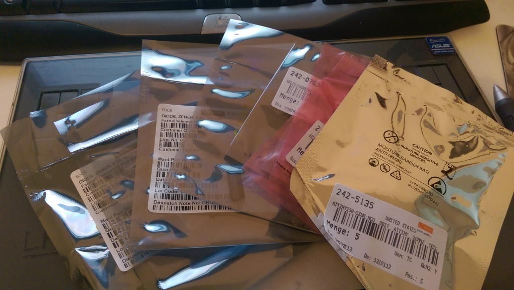
…oh…wait, there might actually be tiny components somewhere inside there! :open_mouth:

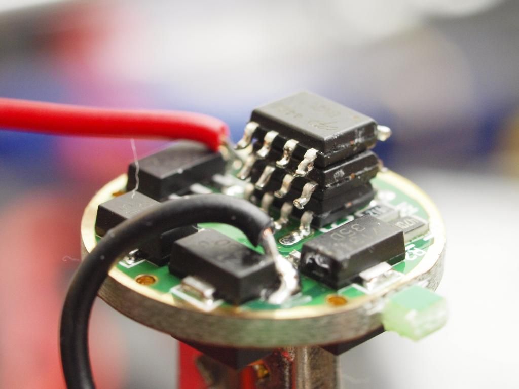
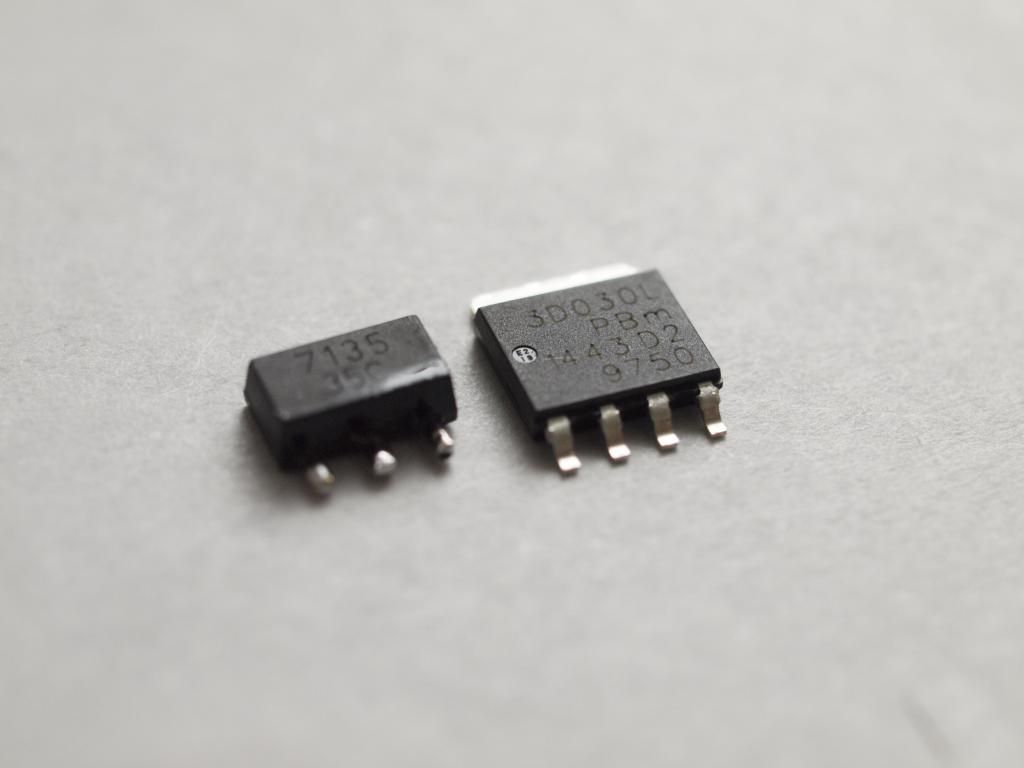
Ahem… yeah remember when I said how I thought those LFPAK fets are a “much much bigger package” than a 7135…well, yeah…not so much. They are properly tiny, can’t believe they can really handle all that current, amazing.

I also got some 5.5v zeners in this order so I will replace the 4.3v one on the MCU board and see how things stack up with a stronger input voltage. Fingers crossed.

The tests I’ve been running to try and track down the dropout voltage of my entire light have been producing really nice predictable results without the MCU, and performance is in another league altogether. It was seriously crippled before, not to mention that extra 0.5v or so being needlessly burned off in the drivers meant I was probably dumping up to 30watts of heat into the driver assembly alone! No wonder I had to over engineer the thermal paths so much, should have realized there was a problem earlier.


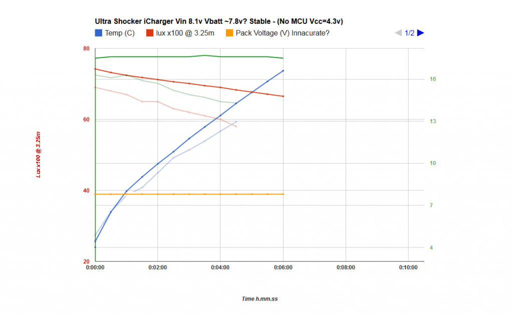
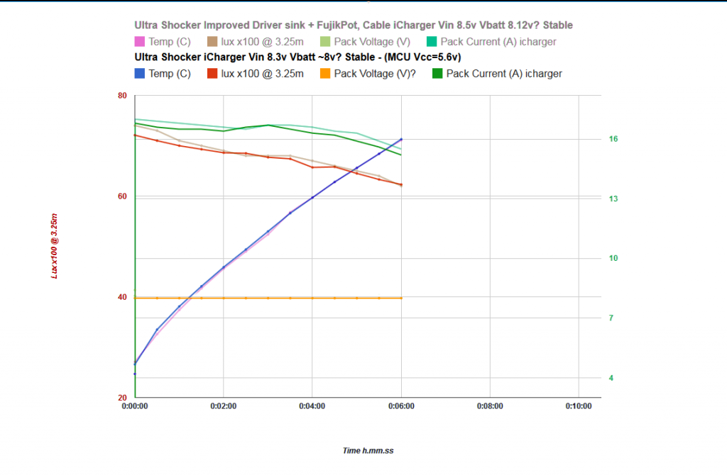
Like for like 8.1v Vin runs. I’m not sure if I would call this fully regulated or not. Currents don’t quite hit the magic 17.85A at any point but it’s close enough and very flat so I suspect it is doing something.
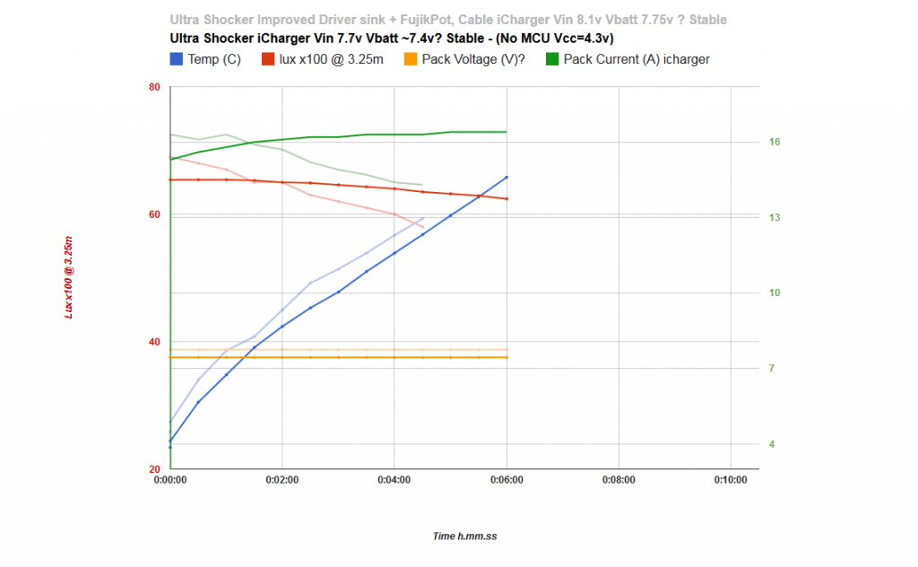
At lower voltages the light tends to start further below regulation and then rise up to flatten out at a steady current. If VBatt is really at 7.8v then seeing any kind of regulation here means I am very close indeed to the dropout voltage I predicted at around 0.8v for the entire light. Which is great.

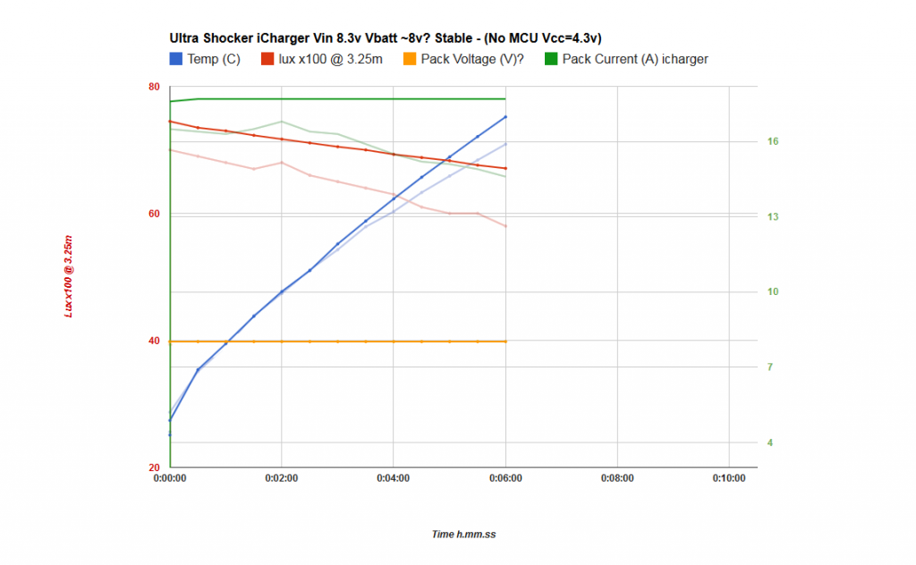
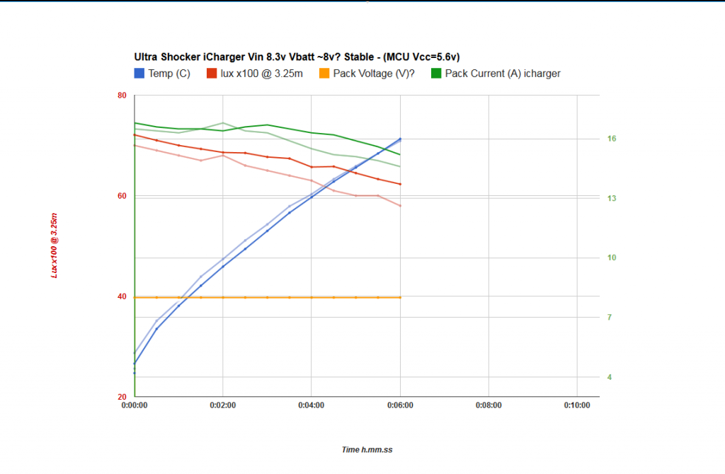
…and at 8.3v, solidly regulated, steady boring graph. Just the way I like them! :slight_smile:

I’m still not 100% trusting the VBatt values but I’ve been measuring voltage drop across the wiring harness instead and that seems to be less prone to variation and weirdness. On average VBatt is about 0.28-0.3v lower than Vin. Thankfully the actual Vin values set by the iCharger are absolutely stable and repeatable so it doesn’t really matter.

Dropping down below 8v iCharger input, which equates to about 7.7v battery voltage and the the light starts to be noticeably out of regulation. There’s no longer much of a flatness to the current graph and it actually starts lower and rises up as the temperatures increase. See the 7.7v Vin (7.4v Vbatt) graph earlier in the thread as to what it looks like when it switches over. But the behaviour is nice and predictable everywhere, I may do some more tests to characterize the light fully at inbetween voltages but meh, it’s a bit of a pain.

At this stage I need to just focus on improving the performance with the MCU active. I have some great comparison data now at these voltage. If anything I do improves the MCU’s performance I’ll be able to see it right away.

Looking good. Maybe a simple PNP transistor would also be a good option for controlling those 7135’s. You’d still have to invert the PWM though.

Hmm, ok, bumping up the MCU input voltage using a 5.6v zener didn’t fix the problem. Although it did make a difference it seems.

Have a look at this before and after graph. Both done at 8.3v with the MCU active, the only difference is the Vcc voltage (4.3v before & 5.6v after)

It’s still pretty bad compared with the MCU less target graph above, but it’s also not identical to the 4.3v version. Quite a bit different/better in fact (the output lux data isn’t accurate enough between test sessions to compare directly but if you look at the current it tells what’s going on quite well)

The shape of the current curve also looked rather familiar so I compared it with the data from the next step up in voltage that is at 8.5v.

It’s a much better fit, so I think I can tentatively conclude from this is that the extra 1.3v Vcc voltage has on average, reduced the dropout across the 7135s by about 0.1-0.2v. Certainly better but it’s still not working right, seems I’d need to drop at least another 0.3v to get it close to the target graph. Flicker was also back with a vengeance right around the 2.5 minute mark, but maybe even a tad worse than before actually.

Poor little Atmel just isn’t up to the task it seems. Looks like I’d better start studying up on p-channel fets :slight_smile:

Cheers
Linus

That sounds like it could be a single component solution? Is that right? I really have no clue when it comes to circuit design beyond the bleedin obvious :stuck_out_tongue:

Could be. I forget, does your switch interrupt power to the entire circuit or just the control PCB? (EDIT: eg does turning off the switch leave the daughter-PCB’s hot?)

Interesting,
Switch interrupts only the MCU power, ie it interrupts the positive line coming from the battery and going to the MCU board.
Battery negative is hard wired to the slave/daughter boards (ground ring) and battery positive is hard wired to the leds + if that’s what you mean by hot.

Hmm, now that I think about that’s OK. The PNP transistor would be used as a “high side switch”, meaning that it interrupts the positive connection, not the GND connection. The problem I was considering is that when the MCU is off, that would allow the PNP’s “Base” to float to GND. When the PNP’s Base is at GND the PNP will conduct from the Emitter to the Collector (yes, I’m staring at a tutorial while I type this ;)). When it’s conducting, the 7135’s are on.

Of course this would be a problem if we were putting the MCU to sleep like in a momentary setup. This would also be a problem if the power switch in your psuedo-clicky was only hooked to the MCU. In this case it’s fine, the PNP will get Vcc / BAT+ from the MCU board and the MCU board will be switched by your clicky. So there won’t be anything for the PNP to conduct, even thought it will close the circuit while at rest…

In other words, no problem I guess.

Oh man, I thought I had it sussed but now my brain hurts staring at transistor diagrams. Emitter, Base and Collector is really throwing me off, haha. Hardly intuitive terms…
Took me long enough to get Gate, Source and Drain the right way around when it comes to mosfets.

-

So on a PNP transistor the Base is sorta like the gate on mosfet right? This leg would be Connected to the PWM pin on the Tiny13A?
Except it’s behavior is opposite to the gate on an n-mosfet in that it will “turn off” the transistor when it is high. Hence the inverted PWM.

The Emitter is like the source and connected to the Vbatt positive on the MCU board?

And the Collector is connected to the Vcc pin on the 7135s?

Hopefully I have that the right way around. Really appreciate the help on this btw, this sounds very promising.

Unfortunately I just had a look through some old circuit boards and I only have one single NPN transistor…damn, testing this will have to wait until I can track down a PNP. :frowning:

I wasn’t joking about keeping a tutorial open when I talk about this stuff. It’s still open, so I’ll check it… yes you’ve got it right, as far as I know.

I don’t know if any of this stuff is local to you, but… Comparison of swiss electronics shops - English Forum Switzerland

I don’t think you need anything more than whatever random PNP you find at a local component shop.

Awesome, yeah I’m sure I can track one down.
Distrelec is not far from here and they have….urgh…only bout 20 million PNP variants… :stuck_out_tongue: It’s never easy with components is it…

Googling general purpose PNP transistor gave me this 2N3906
Only has a 200ma current limit though, that’s right about what the 7135s use isn’t it. Is stacking out of the question? Haha :wink:

I wouldn’t worry about it. The ATtiny13A is certainly not providing 200mA, this will probably be an improvement.

(and yes, in general components can be a huge slog.)

Why not do an attempt with the MCU simply writing constant high on the output pin instead of using PWM? This should be no different than using a transistor to “open” the 7135s.

Not sure I understand how that would me help get my modes back.
Or you mean just to see if the behaviour of the output pin is different in constant high vs PWM?

My understanding of wight’s suggestion to use the PNP transistor is that the transistor will take the load off the Attiny13A’s PWM pin since it will have no problem supplying the needed current to all the 7135s. Switching a single transistor on and off using the PWM pin is going to be much easier on the poor Atmel pin than driving all the 7135s individually and as long as I invert my PWM values I’ll maintain the same duty cycles and modes that I had before. Hopefully :stuck_out_tongue:

Hmm, tinking about this again now. With inverted PWM values surely I’d have to switch to phase correct PWM to avoid running into the strange “not fully on @ 100%” duty cycle issues. Since STAR has those at the bottom of the PWM range they be back at the top for me, right?