I can’t be 100% that the flickering was completely gone, but it certainly didn’t draw attention to itself as much as before.
Strongest flicker was noted when doing the 5.6v MCU test, no sure what that means but the behaviour tends to be pretty consistent between runs.
Well guys, seems the little 5v LDO has really done the trick.
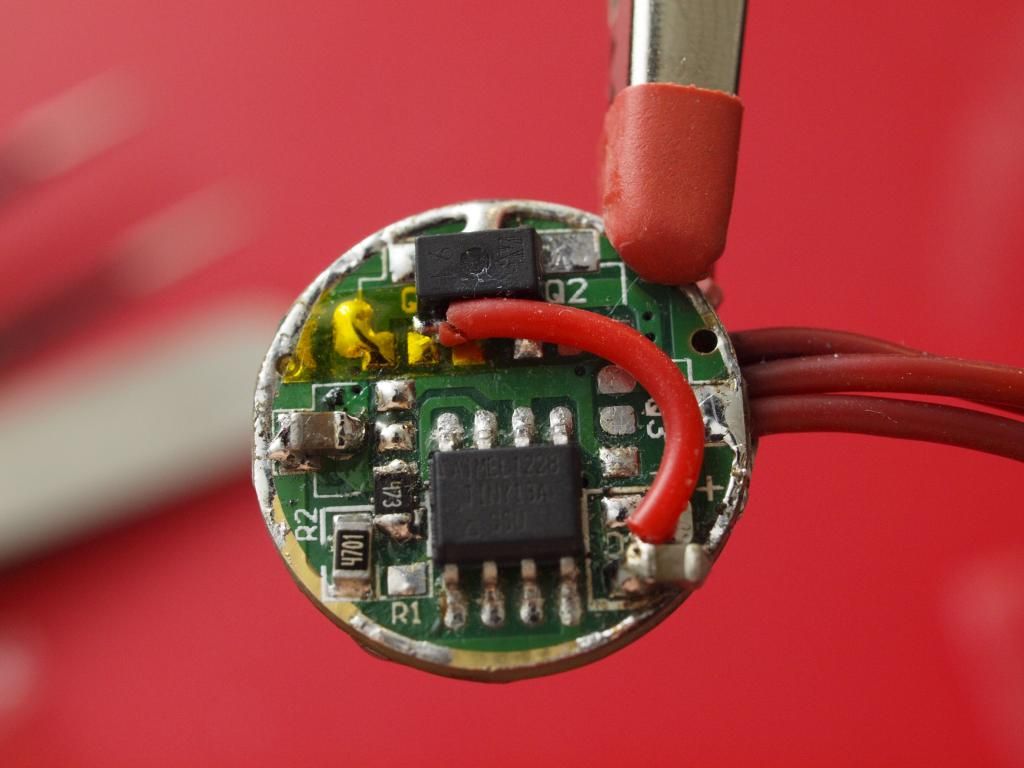
I slapped it onto the MCU board replacing the 5.6v zener and resistor. Hooked up my new DMM to the trigger circuit to measure driver current and ran a test (still using Mike’s firmware with output pin set to High i.e no PWM). The results where perfectly regulated output current at 8.3v iCharger voltage, just like the MCU-less runs!! :bigsmile: :party:
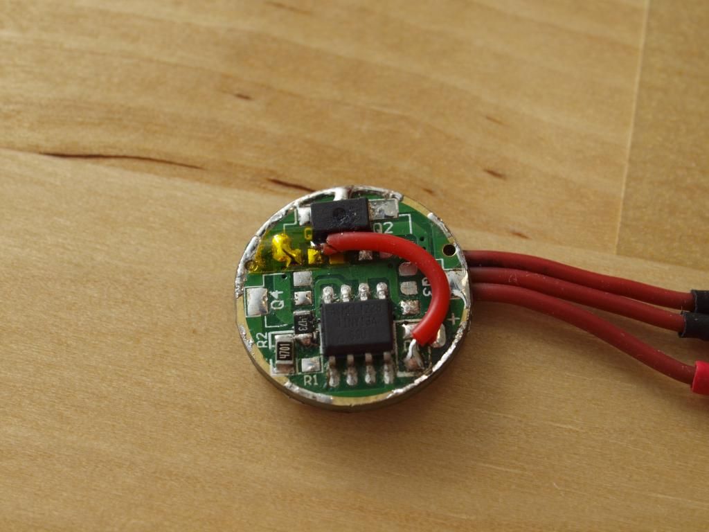
(Here’s the little fella on the board… I’m struggling to still call sot-89 parts little at this stage :P)
Of course I’m a plank and forgot to turn off the cooling fan before starting the test. So I’m setting it up again now and flashing my normal firmware back to the MCU to get some like for like data. Fingers crossed it works as well with the PWM back on.
But I can tell you for sure that the influence of the fan did not make this much of a difference to the drive current. It’s a bang on a perfect match to the MCU less test, flat and steady. ![]()
-
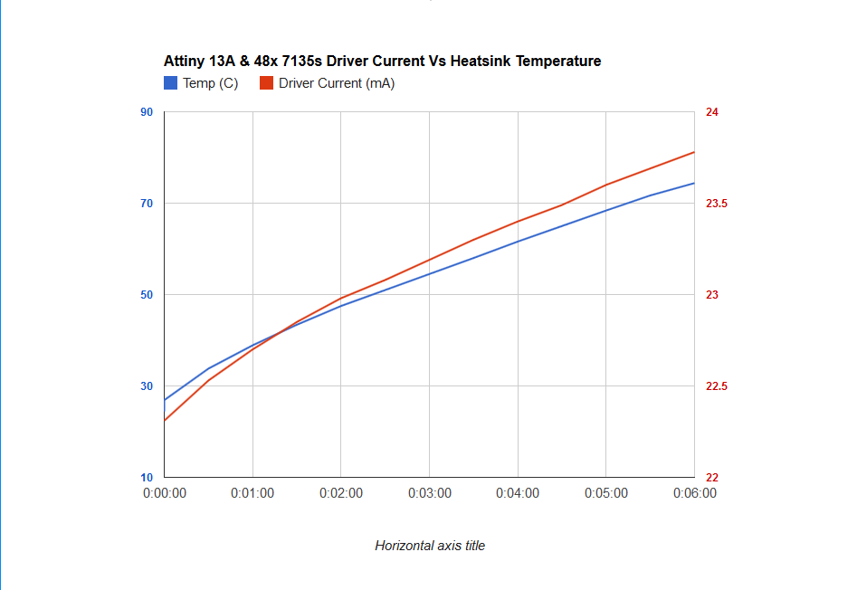
Also interesting are the driver current draw results.
The driver drew 23.9ma at the start of the test and that rose to 24.89ma by the end of the 6mins. Which doesn’t seem all that high to me but I guess it could be quite a bit higher than what the Zener mod 200ohm resistor is intended for. I calculate there to be a voltage drop of 4.975v across that 200ohm resistor with this current draw!
So that doesn’t seem to leave much of an input voltage for the MCU to power itself and all those 7135s. I suspect that could be part of the problem, but let me know what you guys think.
It’s still not a clear red flag but I’d have to check the Attiny datasheet at an input voltage closer to 3v to see where it starts to struggle.
Please correct me if my weak understanding of how the Zener mod works is tripping me up here.
Resistor drops the voltage to the MCU based on it’s current draw, and the Zener is like a safety blow off valve which bleeds off unsafe voltage spikes should the current drop too low at the MCU. Is that right?
If that’s how it works and the higher voltage drop is the cause of the problems I don’t however know why swapping the 4.3v zener for a 5.6v one made any difference at all… :~
-
In any case this is really looking good with the little LDO, i’ll post up a graph with the proper test in a bit.
Yup, standard firmware with PWM (phase correct) works just as good! ![]()
Awesome, really pleased with this. Looks like this is the solution finally!
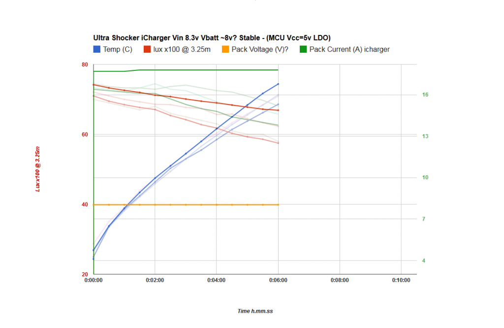
Here’s the graph compared with the other MCU tests I ran, I’ll save myself the bother of pointing out the differences, they’re not exactly subtle… haha ![]()
-
Interestingly the driver looked to be drawing a little less current when operating under PWM (phase correct) compared with the constant on firmware.
Although that could be margin of error stuff between the two tests.
Here is the driver (mcu) current plotted against heatsink temperature.
Amazing effort and loved the team work. I see the lines going up and just think of temperature rising. 
This sounds great!
23.9mA total sounds a little high to me. The MCU and LDO shouldn’t be eating up 3.9mA I think (I could be wrong, I’m not going to go check right now. They’d be close at least.). The Absolute Maximum Rating per pin is 40.0 mA, and we’re far away from that. 20 mA is the normal rating though, and you’re probably sitting right on that mark. Adding additional 7135’s beyond what you have now is probably not a good thing to do. That’s all I’m really getting at, just thought I’d bring it up while we’re on the subject.
Your understanding of the Zener setup is a little flawed I think. That’s OK, I have trouble with it too. The Zener will dump all excess voltage beyond it’s rated (reverse) voltage. The problem is that the Zener is practically an electrical short for all that energy, there’s no limit. So we add a resistor of the appropriate value to limit the amount of current which flows. Note that the Zener we use is only rated to dissipate 500mW (0.5W).
I am actually not familiar with all the considerations that are made when choosing a load resistor the correct way. Here is a resource with some text on the matter: Zener Regulators
OTOH, here are a couple of calculators with no writeups:
http://www.rcrowley.com/zenerreg.htm
They all seem to agree that a 48 ohm resistor is required if a person plans to operate a 4.3v Zener with an input voltage as low as 6.0v and providing 25mA. Or around ~110 ohms would be required at 8.4v. No wonder the thing didn’t work. … that said, I’m not a huge fan of the Zener and I’m happy to see you move away from it to something a bit easier for us to understand.
The calculators show that about half the energy is dissipated in each component (Zener / limiting resistor).
Yep really appreciate the help all round, couldn’t have worked through this without some great comments from you guys.
Oh and pah! With the drivers working properly this thing “barely” gets warm in general use, needs more AMPS! ![]()
-
Yeah and that would mean the 7135s are drawing close to double what the datasheet claims. Good to know ![]()
I knew I had only half the story when it came to that Zener. Thanks for those links, I see there’s a little more to it than I thought.
I think I remember seeing someone use a 100ohm resistor instead of the 200, quite possibly a smart person who knew what to look out for and did the calcs before running higher loads. ![]()
So now that we’ve swapped two components for a little black box of mysteries that poops out 5v.
All works great…except my Offtime memory timing is WAY out, it takes like 30seconds+ to store the last mode. Need to tweak that, hopefully I can simply tweak it far enough in firmware and not have to resort to a smaller cap.
And I’m not even going to hazard a guess as to why this is suddenly the case ![]()
Err, now that you mention it… what are you doing as far as capacitors? Are you following the guidelines in your LDO’s datasheet for input and output caps? Otherwise you may get unpleasant surprises when you attach this thing to a battery instead of your PSU.
It’s been running on the batteries a fair bit now without catching fire… ![]()
It does suggest using 1uF tantalum caps on input and output. I didn’t bother with them, could that be causing the memory weirdness?
Interesting: sure enough, those caps are “suggested”… typically the datasheet demands at least 1uF on the input side.
I do not think that the lack of caps is causing the memory weirdness. (I’d say it’s the lack of easy paths to GND from MCU Vcc.)
Still, it can’t hurt to install those caps. This encourages me to scope an LDO such as LT1761 with 1uF on the input and nothing on the output feeding an ATtiny13A (and whatever) and see what the performance is. Maybe it won’t be that bad.
Done and done. ![]()
Obviously can’t check to see if it’s actually working better but for what it’s worth it still works great! Now to tweak that memory timeout, and then…BEAMSHOTS! ![]()
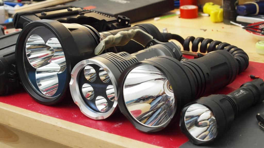
Here’s the lineup ready to do battle. Don’t have many big lights to compare against but the comparison to the 16Amp Apex 5t6 (NW) should give some idea of the flood performance.
Of course I also need to run another test with the batteries instead of the charger and see how it does, that should be interesting.
Hanging for this battle since the start of your build and very excited to see the results
Just for the record… (especially since it worked anyway) I’m told that those caps should be very close to the components they decouple. Without a scope on it I have no idea whether they were even needed in the first place. (eg I have no horse in this race.)
FWIW on the offtime memory thing I’ve been meaning to write a post about it, but I recently had to crank the value to 240 in order to get what I thought was a reasonable offtime period. I started at 145 and got something like 3s, then 200 and that was still no good, and 240 is acceptable.
You know, I’m probably going to finally get my scope in the mail when all of this is working and done, then won’t have a need for it again for like a year, urgh… ![]()
I assume 255 is the limit on the timer there just like the turbo timeout?
I’m a bit worried about that since it takes SO long to store right now, it’s basically next mode memory unless I set it aside for like 30s to a minute. Will see how far I can adjust it.
Otherwise I suppose I could parallel a resistor across the capacitor to drain it quicker or find a smaller cap?
I haven’t tried, but I think the difference with a smaller cap will not be very large. The parallel resistor is probably the way to go. 255 is the limit. The trick here is that we charge the cap to MCU Vcc, then we discharge it for a while (off time), then we compare cap voltage vs 1.1v (internal Vref).
Happy to see the results! Good work indeed. If I understand correctly, you are currently using the LDO to feed the MCU instead of a zener and resistor? You’re not using the MCU to trigger the LDO as a “gate opener” for the 7135s?
All though I like LDO solution (if I understood it correctly), using a lower valued load resistor for the zener could have solved the issue?
Yes the LDO supplies regulated 5v power to the MCU. The Attiny13A is still the only thing supplying power to the 7135s.
I was actually just going to use the LDO to provide a more understandable power source for testing the transistor but it solved the problem directly.
And yes, I believe as Wight said using a resistor with the recommended value based on the required current draw would have worked just as well. Haven’t tested that though since I also prefer the LDO approach to the zener.
-
I’d be very interested if you could do a similar kind of test on your M6, see if there is a noticeable difference in the output current behaviour between the standard zener approach and a 5v LDO. Or just by using the correct value load resistor along with the zener. I’m assuming you used a standard 200ohm resistor as well on your driver?
If you don’t have a current meter that can go to 18A you could just measure voltage drop with your DMM across a current shunt and calculate it that way.
Cheers
Welp, just maxed out my OffTime cap timer to 255 and it still takes around 12 seconds to store the mode! ![]()
Time to do some calcs and find a suitable drain resistor for the cap.
This is now looking like a 4 component solution (5 if you count the airwire ![]() ) replacing the 2 component zener mod… smart or dumb?
) replacing the 2 component zener mod… smart or dumb? ![]()
Right. That’s what I think, at least!
I wish I understood this behavior better.
I’m definitely going to try out switching the load resistor out for a lower one. Not sure I want to dig into the LDO if a lower zener could work.
Not sure what you mean with current shunt (not even novice level at electronics). Could you explain is if explaining to a dummy? Do you mean putting a resistor in series and calculating current through it with Ohms law?
Perhaps it’s worth having a look at at using VCC as reference voltage instead of 1.1V when measuring the cap level in the off time check? The ATTiny13a can use either 1.1V (as default in Star) or VCC as reference voltage in the analog to digital converter used in the off time check. I have never tried using VCC as reference voltage, I have never needed to, but how knows, maybe using VCC as reference voltage when doing the check will get you within a usable range when measuring the CAP level?
The line in the code is: ADMUX = (1 << REFS0) | (1 << ADLAR) | CAP_CHANNEL;
REFS0 set to 1 (as in Star) sets the internal voltage as reference (1.1V), setting REFS0 to 0 sets VCC voltage as reference. I didn’t read enough to make the call myself, but on page 92 in the ATTiny13a datasheet you can read a little about bit 6 (REFS0). You can also read a quick bit on ADC voltage reference on page 88. You’d have to read a lot more if you want to figure it out, or you could just do like I would, test setting REFS0 to 0 and see if you can toggle values to a usable result. Don’t know if this will work at all, just a suggestion after quickly browsing through how the analog to digital converter works. You might have to change more things in the code to get it to work too, I don’t really know.
Yep exactly a low value resistor and Ohms law, that’s how the current meter inside your DMM works. A current shunt is just another term for a very low value resistor designed for measuring large currents.
They can look like pipes soldered onto a PCB, basically just a segment of thick wire with a known and precise resistance.
Ah that sounds interesting, so you’re saying the OTC (off time cap) is charged to Vcc and that it can take so long to register because it has to drop all the way down to below the 1.1v reference voltage? I had assumed it was only ever charged to a low voltage close to the reference to begin with. Thanks, will look into it. It’s probably worth a shot to change what you suggest in the firmware and see if it’s any better.
-
I was curious so I did some more testing with the PNP transistor switching the 7135s. This time using a cleaner test setup and some basic 3 mode firmware.
(Turns out I did have a 70ohm short on the 7135 driver puck I was using for the last transistor test…doh! :~ )
I set it up with the 5.6v zener first but then switched to the LDO, behaviour seemed similar between the two but I only tested the simplified firmware with the LDO.
Overall it works but not 100%. First of all mode memory seemed to be broken so I switched that off along with LVC and just tested basic modes. Low modes (below normal PWM of around 50 or 200 inverted) don’t seem to register as lower. If I set up something like 10, 50, 255 (non-inverted) then the 10 and 50 are basically at the same output level, very hard to tell the difference by eye. Occasionally (maybe heat related) or if I pinch the transistor legs with my finger I can get the low mode to drop down further than medium but in general it seems to plateau at the certain point and not want to go any lower. Same applies to any kind of moonmode obviously.
I also noticed a behavior where switching to a lower mode caused a quick brighter flash just before it dropped down.
Medium, High and any flashy modes work perfectly though, so if this were a chinese driver we’d call it a day and send it to the assembly line… ![]()
I tested with both Fast and Phase correct PWM, made no difference. So unless I’m doing something wrong I don’t think this is a straight forward single component solution to driving a bunch more 7135s. Shame, I’m looking forward to scoping this test setup though and seeing what brings on the plateauing behaviour. I also neglected to add the filter caps to the LDO so maybe that had some effect too.