I tried changing the Vref in the code but couldn’t tell if it made any difference. Maybe I did it incorrectly? I didn’t test it particularly thoroughly before going after a hardware solution.
I set up a little test rig and tried out a bunch of different drain resistors to drop the charge on the OTC faster. (are these technically called pull down resistors?)
I settled on a 220kOhm resistor in the end, short click timing is now quite fast but I can always tweak that a bit further in firmware. Certainly anything that isn’t a very fast half press will now be stored and the light reactivated in that mode.
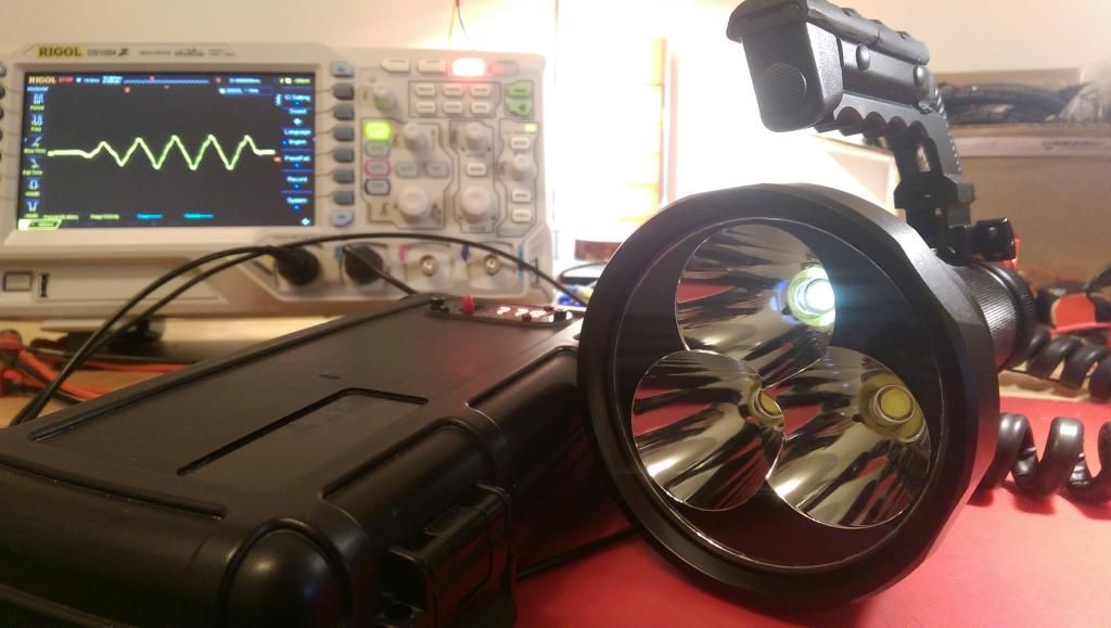
Phew, looks like this is the MCU board finally working right. Still need to fine tune the LVC but that’s not as critical at the moment.
Nice, looks like it’s coming together! A single pull down resistor is an easy enough solution. Is it simply connected parallel over the cap?
And also, the temps you have taken now, are they taken exactly as in post #240? It takes your light about 6 minutes to reach 70C? I’ve gotta do some temp testing on mine. Gotta wait though, I’m in the middle of redesigning my driver… again. Putting 48 chips on a single board with a separate channel for each LED and having 4 groups of them for the each of the 4 output pins on the MCU, all on a two layered board is quite a challenge. I got it all in with not so bad ground and LED- traces after a lof of work… and only then when it was all done did I realized that I could get a 30 day trial test of Eagle to make a 4 layer board design… so now I’m starting over again with 4 layers.
I’ve just got two additional M6 hosts in, so I’ll be building a new one with the new driver and do some testing. May I ask how you are doing your lux tests? What are you using? You may have posted this before, sorry if I’m a little too lazy to read through it all to find it.
Pulldown resistor: Yep just soldered on top or in my case on the side of the OTC.
Temps: Yep temp measurements are taken exactly the same way using an IR thermometer pointed directly at the Heatsink fins, on high it now takes 6minutes to get to about 75degs C yes.
Board design: Is it an unforgivable sin to just use airwires instead of traces… haha… can imagine that would make things quite a bit easier Look forward to seeing your results on this in any case.
Lux: I’m using one of those cheap and crappy red luxmeters you can find on ebay. It does the job but it’s not particularly repeatable or reliable.
-
On the transistor front (couldn’t leave it be :P) I decided to measure current draw of the 16x 7135s on my test puck. Again just to verify how much they actually draw and play around with the PNP approach again. Surprisingly with the transistor driving the 7135s and measuring the current between the LDO and the transistor I saw a massive current draw of over 90ma!! Something not right there. Looking a bit closer and measuring current across the individual legs of the PNP I noted that the vast majority of this current was passing between the Emitter and the Base leg . The 7135 driver puck itself was only drawing about 7ma while the rest was being sunk into the MCU pwm pin. Makes sense since in 100% duty cycle mode the MCU is holding that pin low and without any resistor in place it’s drawing quite a bit of current. Not sure if that’s good for it, certainly it’s about double the max allowable output current per pin…
In any case I found that adding a 1.5k resistor between the Base leg and the MCU pwm pin allowed the transistor to still pass the full 5v onto the 7135s (i.e remain fully on) and reduce the total current consumption down to around 9ma. Much more reasonable. If the base resistance value is too high then the voltage on the 7135 side of the transistor dropped below 5v so that’s probably an indication that the transistor was no longer fully “on”.
I do remember coming across a calculator to work out max base resistor values for specific transistors, didn’t know what they were for at the time but now it makes sense.
In any case I learned something new about transistors today!
Yep pretty major one, turns out I never actually flashed my test version of the firmware with the OTC maxed out to 255. Or indeed the subsequent alteration of it to test the Vref… Urgh, thought I had moved beyond making silly flashing mistakes like this…
I realised what I’d done after it was tripping me up for 30 mins now, I thought I’d zapped the MCU and broken it because it suddenly didn’t have any modes at all after updating my latest firmware to 255 timeout. Assuming that value had worked before on the alternative version and even been used to tune in the pulldown resistor. Really Dumb.
But at least now I have my pulldown resistor working and it was actually fine tuned on a firmware version that had the default 130 OTC values. Meaning I have an even better adjustment window than I thought, both up and down if needed.
-
LVC is also dialed in now to step down at 6.5v and start ramping off at around 6.1v. Should be nice and safe for these packs.
Don’t you just love that moment in a project when your light gains sentience and starts designing itself?
Mines just developed a permanent standby moon mode on one emitter…all by it’s self. I’m so proud…hah!
-
Well, I checked to make sure I didn’t have a short between reflector and led -, or somewhere on the driver. So my best guess is that a 7135 chip has failed in a partially on mode. Anyone seen this happen before?
I guess that’s the risk of having the leds “live” all the time and relying on the 7135s to remain fully off when no power is applied to the MCU.
That is also the emitter that had the flickering issues before the LDO fix so maybe that one 7135 responsible for the flicker has been cooked half to death during all that testing. The regulators where certainly getting way too hot during those early test runs so I guess it’s not too surprising.
No way I can indentify or swap it out if that’s the case so I’ll have to live with this on-mode status LED. It’s the center one and everything so it almost looks intentional, haha
Well it’s either that or the light’s jealous of the thing in the background that’s been occupying my attention today
I’ve paid much more attention lately when running my light and have noticed some flickering also. Thought I’d let you know as earlier I had not. I’m going to try lowering the value of the resistor and see it it makes a difference, at least while I’m waiting on my new PWM-less driver som OSH Park.
That’s very interesting, yes please let us know what affect a lower resistor has. #
And I’m very sorry that all this talk of flicker has caused you to notice a subtle issue that you may not have ever seen without looking for it…very sorry
Haha, don’t be. I’ve learned quite a lot from following your thread. If all I have to do is easily swap a resistor I will have greatly benefited from your issues. I’m going to do the firmware test with constant on/high first, just to see if my flickering can be hammered out without PWM as my PWM-less board is in production. I’ll be adding a lower resistor anyway of coarse, but it’ll be interesting anyway. If it works I could just recode the software to do constant on/high on my highest mode and PWM the others until my new board arrives, but will do both tests anyway. I’ll be adding the test results in my own thread when I get ’em done.
Yes if you’re light is anything like mine, the constant on pin should eliminate/reduce the flicker. BUT at the the expense of lowering the driver performance even more! In my testing the runs with your custom firmware where the worst performers overall. So if MCU current supply is also the issue on yours then simply changing the resistor will solve all the issues in one.
High (100) with fast PWM shows absolutely nothing but a constant solid output when I scope these STAR drivers, confirming what Wight and JonnyC and all those have said. So with the right power supply in place (modified zener or 5v LDO) there’s not going to be any difference at all between setting the pin to ON or PWM 100.
I decided to just try and solve the issue instead of doing the experiment with the firmware (which would result in performance loss), so I soldered on another 200 ohm resistor to get down to 100 ohm (didn’t have anything else lying around). And it solved the flickering… At least for as long as I had it on, which was a lot longer than the time I had to wait to see flickering. I did not re-charge the cells between the tests.
So… my flickering was a quick fix, thanks to you and wight. Basically you guys did all the head-scratching and testing, and I’m just taking a free ride. So I extend my gratitude, thanks guys
I’ve got 50, 75 and 100s on the way with my next component delivery, I’ll run a few calculations through the zener calculators wight provided and see what I end up on using, but lowering the resistance certainly seems a must.
Awesome! Nice to hear similar results with reducing the zener resistor! So now there’s two solutions to this problem, and your M6 photon blaster just got a healthy boost in sustained output and runtime!
If you have the time, it’d be interesting to make up a little table showing what zener mod components you need to run a certain number of 7135s. Just theoretically using that calculator and based on the 7135s drawing about twice as much current as is stated in the datasheet. Maybe something to add to the popular stickied zener posts.
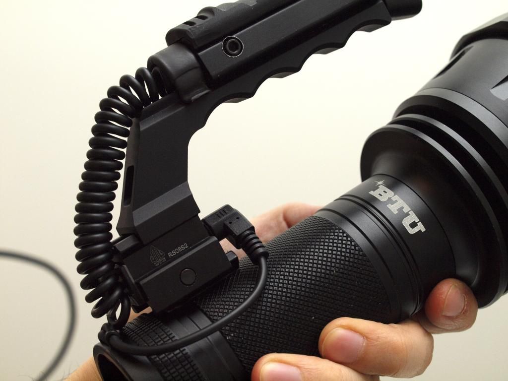
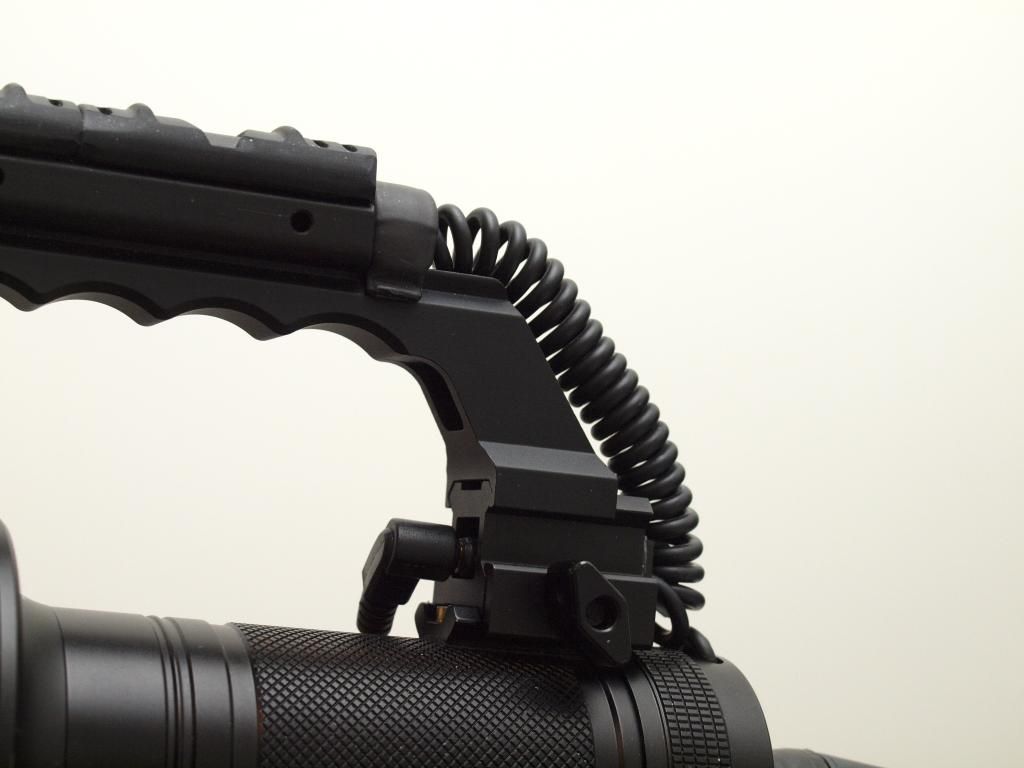
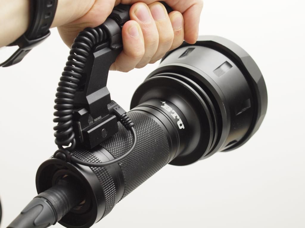
Just tying up a few loose ends and completing the handle. Added a 2.5mm jack to feed the clicky signal into the body of the light. Now easy to remove the handle completely.
I actually planned to mount the socket into the tailcap with the male plug on the end of the spiral cable, but I couldn’t really figure out a nice way of doing it without the plug end being a bit messy and the socket a nuisance in the way of removing the main power XLR.
This alternative works quite well and it keeps out of the way nicely in normal operation, but still if the handle needs to come off for whatever reason it’s a doddle.
Other than that I’m sorta seeing the end of this one, the to-do list is shrinking.
I’m still waiting on parts for the blower rig to get here but I’m sure I can find something that still needs doing in the meantime…like some beams that need shooting or something