BTU Shocker Triple MT-G2 with a twist -- Aiming for >100Watt ~9000Lumens -- With external 2S power pack, handle etc...

I decided to just try and solve the issue instead of doing the experiment with the firmware (which would result in performance loss), so I soldered on another 200 ohm resistor to get down to 100 ohm (didn’t have anything else lying around). And it solved the flickering… At least for as long as I had it on, which was a lot longer than the time I had to wait to see flickering. I did not re-charge the cells between the tests.

So… my flickering was a quick fix, thanks to you and wight. Basically you guys did all the head-scratching and testing, and I’m just taking a free ride. So I extend my gratitude, thanks guys :beer:

I’ve got 50, 75 and 100s on the way with my next component delivery, I’ll run a few calculations through the zener calculators wight provided and see what I end up on using, but lowering the resistance certainly seems a must.

Awesome! Nice to hear similar results with reducing the zener resistor! So now there’s two solutions to this problem, and your M6 photon blaster just got a healthy boost in sustained output and runtime! :slight_smile:

If you have the time, it’d be interesting to make up a little table showing what zener mod components you need to run a certain number of 7135s. Just theoretically using that calculator and based on the 7135s drawing about twice as much current as is stated in the datasheet. Maybe something to add to the popular stickied zener posts.

Just tying up a few loose ends and completing the handle. Added a 2.5mm jack to feed the clicky signal into the body of the light. Now easy to remove the handle completely.

I actually planned to mount the socket into the tailcap with the male plug on the end of the spiral cable, but I couldn’t really figure out a nice way of doing it without the plug end being a bit messy and the socket a nuisance in the way of removing the main power XLR.
This alternative works quite well and it keeps out of the way nicely in normal operation, but still if the handle needs to come off for whatever reason it’s a doddle. :slight_smile:

Other than that I’m sorta seeing the end of this one, the to-do list is shrinking. :slight_smile:

I’m still waiting on parts for the blower rig to get here but I’m sure I can find something that still needs doing in the meantime…like some beams that need shooting or something :stuck_out_tongue:

Cheers

great work!

Where’s the beam shots??

Still looking plenty stock & sharp.

Where did you get the coiled cable if I may ask?

You want a beam shot here’s a beam shot.

Happy? :stuck_out_tongue: :bigsmile:
They’re coming though… Just taking a while cause the light is still being worked on and it’s often not in a workable state. For example at the moment the battery pack is in pieces again as I’m swapping over the relays for mosfets with some control circuitry.

Thanks guys! :slight_smile:

I assume you mean the small switch cable and not the power cord? For the small one look on Ebay, just search spiral usb cable or spiral/coiled charger cable or something like that. Lots out there of various lengths and connector types.

Sorry, I forgot that your design is with an e-switch, the coiled cable is not carrying the juice.

Technically it’s not an e-switch. It’s a reverse clicky connected to the MCU side of the driver circuitry with the coiled cable.
But you’re right it’s essentially like an e-switch and the small coiled cable only needs to carry the 30ma or so that the MCU requires to run.

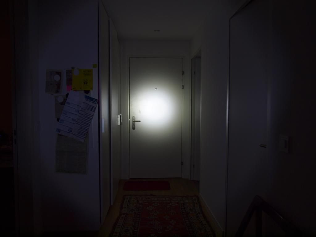
So I threw some photons down my corridor and got these beamshot comparisons. Granted they’re not the greatest, outdoorsy, “losing two toes to frostbite” kind of beamshots but it’s a start right? :slight_smile:

Note: My camera does exaggerate tint differences a little bit, (errs on the side of too green) but it’s actually quite a good interpretation of what the true output is doing. It doesn’t sugar coat tint differences, if the dedomed light is erring on green then my camera will tell it that to it’s face! :slight_smile:

-

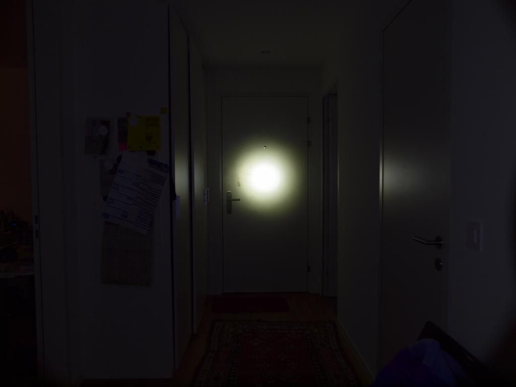
Let’s start with the dimmest. My Convoy S3 EDC. XM-L2 T6-3A : 3Amps

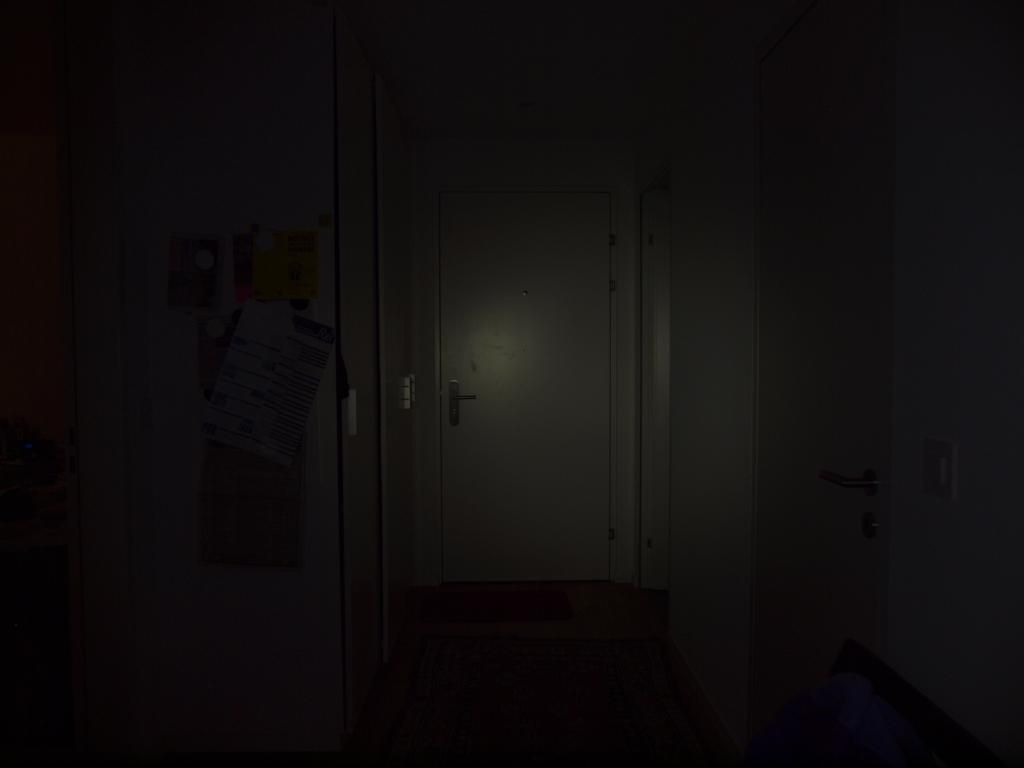
210 lulz @ 4.5m Is this thing even on?

-

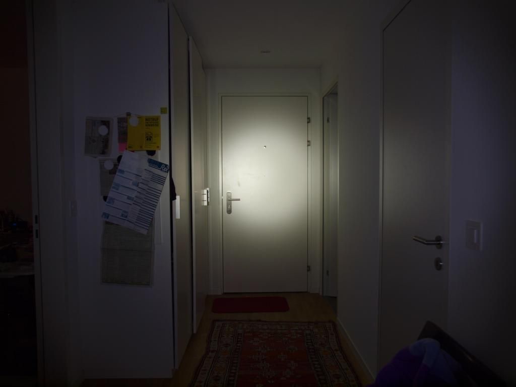
Next up the bone stock Ultrafire F13: just as the chinese design masters intended. :stuck_out_tongue: XML T6-1A/C? : ??Amps

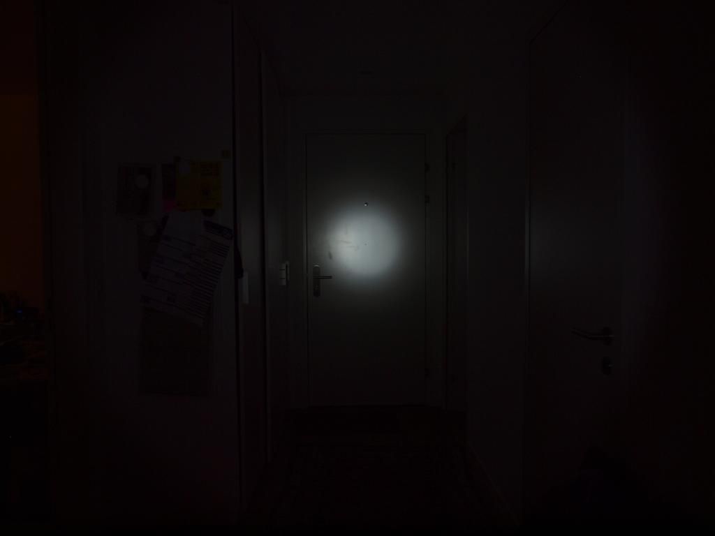
520 lux @ 4.5m Pretty crappy and very blue.

-

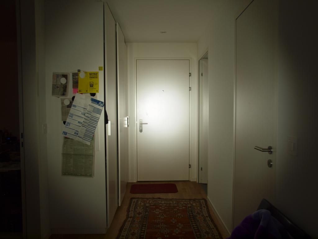
Now for the usual C8 candidate: Ultrafire C8 SMO reflector Dedomed XM-L U2-1A : DD A17DD ~6-7Amps

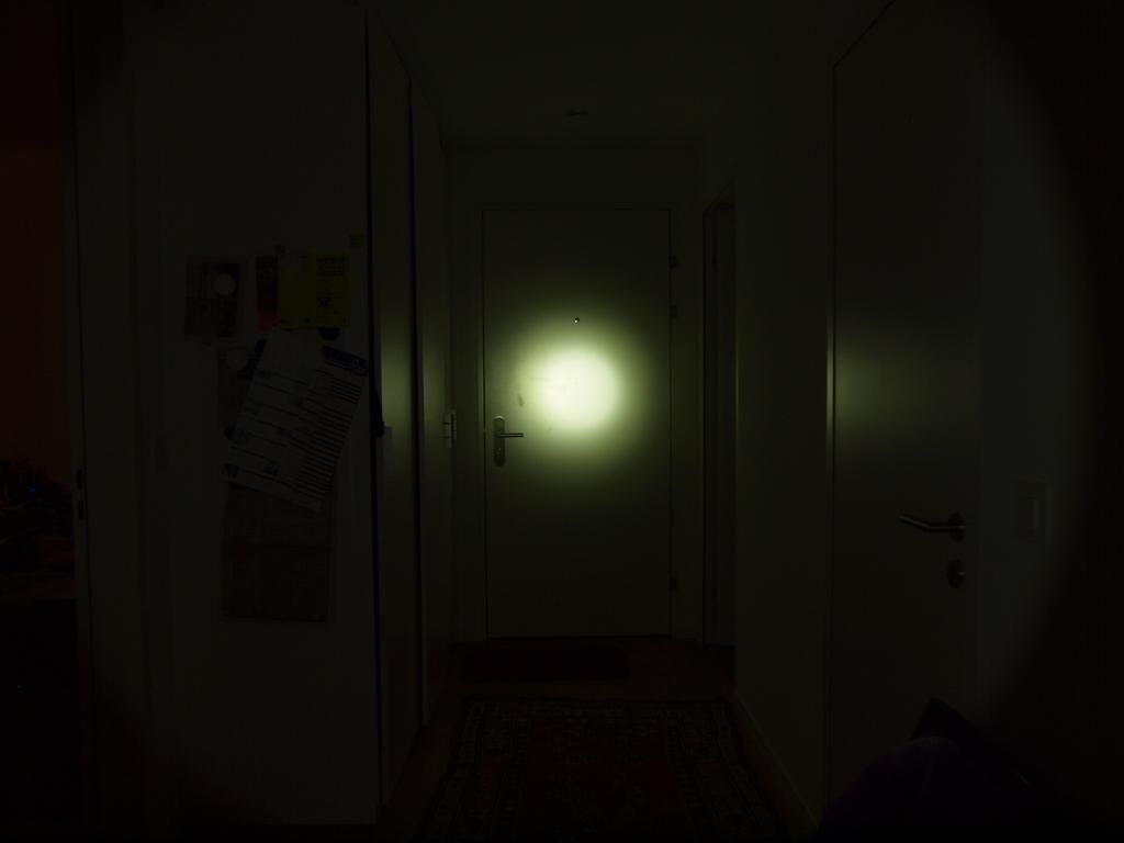
3,300 lux @ 4.5m It’s a fairly green emitter but not too objectionable in real life. I quite like it.

-

The mighty Courui D01: XM-L2 U2-1D : 5.9Amps Mod Thread here

5,990 lux @ 4.5m Naturally the big head comes out on top in terms of max Lux in this test.

-

Modded Apex 5t6 5x XM-L T6-3C : ~16Amps Mod Thread here

2,020 lux @ 4.5m This is my highest output light bar the BTU so it should give a decent comparison. Floody 5x NW XM-Ls in p60 sized reflectors running around 3.2A each.

-

UltraShocker v1.0 3x MT-G2 P0 5000k: 17.85Amps

4,380 lux @ 4.5m Well…it’s bright!

But note in particular the slighty narrower overall beam profile, tighter hotspot and and much brighter spot/spill compared with the 5t6. This light is a real flood monster with a very usable beam distribution. Using it out and about I’ve also come to appreciate the narrower nature of the beam thanks to the deep reflectors. It’s much easier to direct the flood with this kind of light rather than blind everything in front of you no matter what. Plunger lights with shallow reflectors just put out a wall of light, this puts it where you need it most and makes the most of the >9k lumens. It’s very usable (thank christ for that, I didn’t want this to just be a glorified shelf queen after all this! :p)

At this range it also out throws everything except the Big head which is a fair achievement I reckon. Of course I’m still interested in finding out at what range it can actually outclass the C8 when it comes to outdoor spaces.

Did I mention the lovely tint! The differences may be a bit exaggerate in these photos but the gen1 NW XMLs look positively sickly in comparison. The nice even NW beam of those mt-g2s, man it’s just about perfect. Biggest benefit of those emitters by far, just can’t get enough of it! And so even across the beam, no purple spill and yellow hotspot here! :slight_smile:

So hopefully this has gotten the beamshot junkies off my back for a while. :wink:
I will eventually get out and do some proper long range comparisons (when the snow melts a bit) but for now this is it.
Cheers

Man that tint is beautiful! Thanks for the beamshots mate

Nice beam profile!

I’m really pleased with it tbh, outside it just sort of “puts” the light where you need it without any annoying tint variations or distracting hotspot falloff. Nice and balanced flood with decent reach, plus there’s so much light that the faint edge spill is enough to light up the ground at your feet. Just enough to avoid stepping in anything nasty. :stuck_out_tongue:
I thought that might be a bit of a problem with the deeper reflectors projecting a narrower spill beam but it’s not an issue in practice.

Shall we start a fundraiser for a heavy jacket so you can step outside and get beamshots for us?

Oh also I want your BTU, please send asap. Kthxbye.

Not a bad idea, I’ll put up the kickstarter page! :wink:

I got a stock BTU shocker in today so just out of curiosity I took a shot of it in the same setup as the other lights above.

Everything stock, XM-L T6-1As (I think) and it was drawing about 4.5amps at the tailcap during this test.

(Mouseover for Ultrashocker comparison)

4,250 lux at 4.5m (slightly lower but pretty much on par with the MT-G2 BTU at this range )

Small update on the blower module.

Dremelled and filed a little recess on the back of the “duct” to mate up with the case on the blower.

Then nestled neatly inside is the boost circuit to up the fan supply voltage to 12v or 13.5v or whatever lets the little blower blow it’s guts out properly. :slight_smile:
It was a little anemic simply running off the <8v battery voltage directly so this works well.

Admittedly the boost circuitry is WAY overspecced for the measly 5Watt draw of the blower but I had these laying around and it fits in there perfectly so why not use it.
Doesn’t even get in the way of the airflow all that much, although I did have to reposition and replace the SMD output cap with something a little more streamlined.

In the end there will be some more control circuitry installed in the corner of the elbow. An external pot/multiposition switch for the manual speed settings and a temp sensor controlled auto mode that will automatically ramp up the fan once the heatsink temp rises above a certain point.

heh. :slight_smile:

A couple dozen more hours into this thing and a copious amount of structural electrical tape is slowly being replaced with actual fitting parts and functional wiring :slight_smile:

I was so glad when I managed to downsize and transfer my breadboard circuit into this thing and still have it work as expected. Anyone who values neat electronic circuit design should look away now :wink:
It’s more than a little messy in there and got quite tricky getting it all connected up.

On the front of the boost PCB I’ve squeezed in an upside down opamp and a small trimmer pot. The op-amp boosts the output from the temperature sensor and fine tuning of the sensitivity of that control circuitry is dialed in with the pot.
On the back of the pcb is a simple linear fan speed controller. Basically just a PNP power transistor and a control NPN transistor which is automatically driven by the temp sensor through the opamp to ramp up the fan speed in relation to the temperature rise.

Finally I have an external control switch that’s controlling the boost pcb output directly. Basically just a low/high control which replaces the adjustment pot on the DC-DC converter with fixed resistor values.
Low turns off voltage boosting and feeds max battery voltage (<8v) to the fan, and high turns the boost circuitry up to ~14v for a bit more forceful cooling. Both are still automatically throttled by the temp sensor so I may look at adding a manual override option as well.

Functionally the circuitry works quite nicely at this stage save for finding a good mounting location for the temperature sensor itself (it needs to touch or come very close to the pill/heatsink ideally, but if that isn’t feasible I can still boost the output/sensitivity to make it respond at the correct temperature thresholds) and adding another power jack to the light somewhere to power it all.

I’ll be doing some tests on the effectiveness of the blower and the “cooling sleeve”.
As it stands there is simply a window cut into the sleeve right where the elbow part joins up with it, allowing the majority of the air to pass directly over and around the cooling fins hopefully creating a bit of a vortex. However I haven’t done anything more to better direct the airflow and it’s able to leak out around the entire circumference of the sleeve.
I suspect trapping the flow and passing it as fast and as far as possible over the limited fin surface area would yield the best results. So I will be trying a few things like blocking off parts of the sleeve-to-fin gap to force the air to travel around more of the circumference of the light and then offering it a good exhaust path. Seeing how stuff like that affects the overall cooling performance.

If I’m really lucky I may be able to get it working well enough to allow continuous operation at full power output without overheating the light. But that’s probably an unrealistic goal.
I just don’t think there is enough surface area on those fins to really shed the massive heat quickly enough no matter how much air you force over them.
But it will be fun finding out that’s for sure! 8)