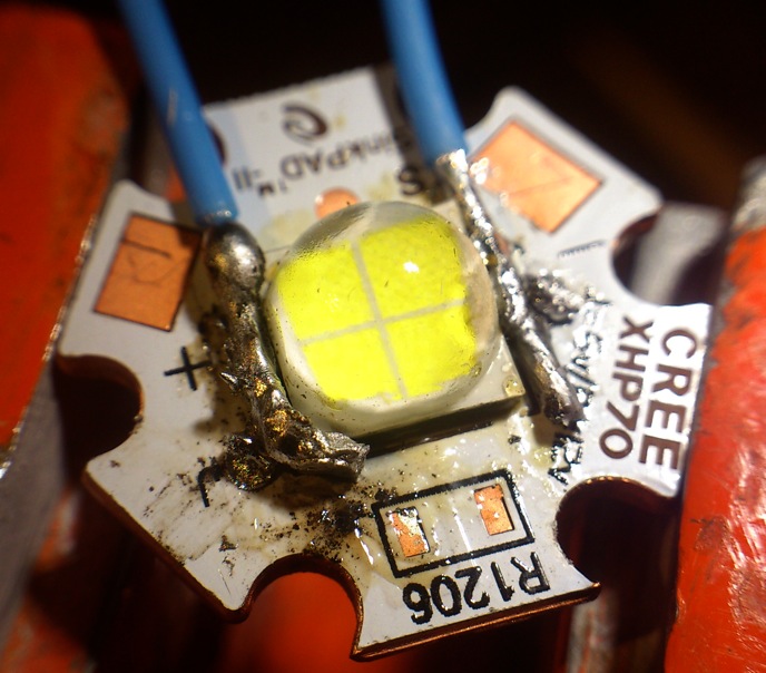
I tested the XHP70 again last night, now mounted on a XHP70 Sinkpad, with the romantically wandering traces avoided by scratching some masking away, does not look pretty but it works alright. What is most important is that the thermal path of the middle pad has improved compared to my makeshift board using a XM-L Sinkpad and copper bits.
It is the exact same led as the first test and I plot the results together the makeshift board results because that is pretty interesting: at high currents this led really wants a good thermal path:
As you can see, the led has suffered somewhat from the 15A treatment of the first test: the output is a tad lower and the voltage a bit higher. But over 6.6A that effect is taken over by the better thermal path of the XHP70 board. It maxes out now at 11-12A.
Still my numbers are very low compared to Dale's numbers, so after cooling down I did some quick tests that were done more like how Dale measures with his flashlights: still the board was on the copper mount but there was no active cooling (fan out), and I went straight to the target current (I tested 8A and 12A), then looked for 1 minute every 10 seconds at the light output:
8A 0 seconds
5340
8A 10 seconds
5280
8A 20 seconds
5230
8A 30 seconds
5190
8A 40 seconds
5140
8A 50 seconds
5100
8A 60 seconds
5050
12A 0 seconds
6631
12A 10 seconds
6258
12A 20 seconds
6164
12A 30 seconds
6024
12A 40 seconds
5838
12A 50 seconds
5744
12A 60 seconds
5557
That helps! apparently at very high currents there is a noticable difference between measuring at 30 seconds and measuring at 'steady state' like I do in my tests. These numbers look a bit more like Dale's, and any difference leftover I am willing to explain by different calibrations or differences within a led bin , or he used a different bin. And my led was already tortured, as can be seen in the graph above.
To get the maximum out of the led I turned the current from zero to 15A in a moment and for a nanosecond I measured over 7000 lumen.
My numbers were from an actual light build, reflector, lens, batteries, real world. So you’ve proven that the losses compute and the emitter is capable of some very serious output. Thanks Jos! :bigsmile:
I was beginning to wonder if that test of mine had been a fluke or something.
15A power supply! That's pretty sweet. I have had mine go up over 10A before, but it's only rated for 10A so I'm not sure if something will break or go nuts if I push it that hard. I have used a buck converter to push the MT-G2s over 13A with the power supply at a higher voltage, but not direct drive.
Looks like after 9A-10A you're not getting much more output.
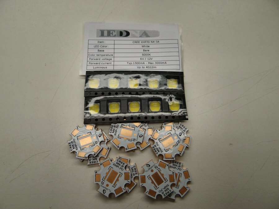
My XHP70 leds came today! LEDDNA sent me 10 of the 5000k XHP70 N4 3A leds. I already have the mcpcbs and the patients waiting on surgery, so it's going to be a long week-end. Billy did a great job of getting them out and they were packaged well and arrived quickly.
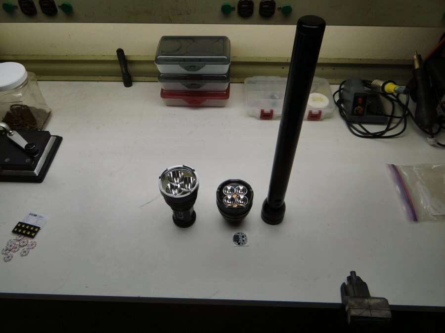
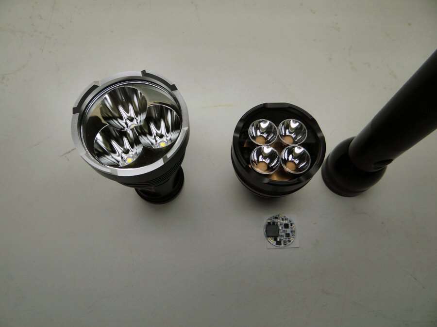
The four up is a light that used to be 4xP7 leds. Now it will be 4xXHP70 leds in series, with one of George's HBFlex drivers and a 6D Maglite with 5x26650 cells in it. 3 amps per led.
The other light is the SP03 and it will have 3xXHP70 leds at nine amps each. Well, maybe... I think it will have a custom FET driver in it, done by RMM. Not positive yet, maybe a 7135 driver.
Thanks for that testing djozz, i have been wondering why Dale numbers is often higher, but the differences between your usual testing in steady state slowly ramping up the output and in flashlight blast at full power directly like he does it explains a lot.
O-L, do you plan do diffuse the reflectors to help eliminate the donut hole? Wondering if you’d use your patented clear overspray technique. Been thinking about that…
LEDDNA is pretty quick, and they had bins not available elsewhere. Rock on!
I don't know yet, if I have to, I will. I plan on doing some testing with a few reflectors I have laying around and see what happens. I plan on doing one led raised off the star surface, with copper, so I can try some different heights of reflectors, to see what effect the it has and see if there is any way to minimize the X mark. I will post the results, with photos.
Thanks Djozz, very useful graph as always! Seems like 10A is a pretty decent spot to run these LEDs at.
Would it be possible to also measure the heatsink temperature in your usual test? As it seems to have such a large effect on the output it would be interesting to see how the heatsink temp ramps up in relation to the the current ramp.
When I first tested it the cells were at 3.95V, almost dead, after the lightbox run. I didn’t run it just tested it. The first reading I got was 12,523 lumens.
So of course I charged the little cells!
13,903.5 lumens out the front, even low does 1408.
I lined up the emitters such that the line between dies pointed towards the middle. This put them diagonal to each other. And the donut hole is there at low, but decreases as the brightness goes up. Turbo is a stupid amount of light!
These are the 6500K variant, the first ones out.
This Toshiba is a new release, it has a plate on top like the one on bottom that solders to the driver. This is supposed to help with heat. It’s rated at 150A, 30V.
Can’t help but wonder what a good set of top end 18650’s would do….