5 is the lowest value ? or you can go 1?
This
I really don’t understand the mechanics of it, but personally I’ve never had an LED light up under 3. I usually use 4 or 5 for my moon modes.
You can go down to 1 with a single 350mA binned 7135. Sometimes the 380mAs require 2.
Remember, I'm talking about a single 7135. As the number of 7135s increases, so does the minimum PWM level required to have them turn on and be stable. Again, this makes sense when you remember that the 7135s are wired in parallel and powered entirely by the PWM signal.
ic ,thanks.
Ok, i got it now, the thing that got me thinking that 255 on the FET still was PWM’ed, was that someone in TK firmware repository thread, claimed that it was, and i don’t remember anyone corrected them, so i got confused.
So the 255 PWM signal/value isn’t a PWM at all it, is just a value to tell the chip to go fully open & NOT PWM the output ![]()
I have read in other places that getting a set of stars on these is not possible because of space requirements, but I am wandering is there any possible way to squeeze in ONE??
I would like to use the boards in large batches, but having to ground out any of the micro pins from the top totally eliminates the possibility of pre assembly.
Not sure where you read that, but it is definitely possible (and not even that difficult) to add them. Most of us have just found them to be superfluous in this type of a driver since you are building it from the ground up anyways.
Hmmmm... I think where I got that impression was from the original BLFDD17 thread, but I suppose I could have misread it.
That said, AWESOME! I have a few more details to work out, but I think this is going to work very well for my setups. Thanks RMM..
Built my first one of these drivers using the "800" FET (forgot exact P/N), using the T_K blf-a6 program with minor tweaks. It's in a Convoy C8 host, the original one.
I noticed a significant blink when switching between hi/turbo (full out FET only) and moon mode (PWM value of 4 for the 7135 only). Anyone else notice this strange behavior? I know I've seen this before in some troubling drivers - pretty sure it happened with my stock BLF Mini-01 driver.
That's the SIR800DP.
Regarding the blink---I've seen it before on the BLF10DD/12DD drivers when switching from high to moonlight. That was with the same firmware though, so I'd try and rule that out first, although I haven't heard of anyone else having issues with it.
I fixed my problem with a small pulldown resistor (30K) from the gate to ground. You could try a 22K or 19.1K (you've probably got one on hand) and see how that works. If it doesn't get rid of it, you could double stack resistors to half the resistance then try again.
Thanks Richard! Think maybe it's a side effect from this SIR800DP FET used in this fashion? I'm think'n the "gate" is pin #4 on the FET? Looks like pins #1-3 are all goin to ground, so could just put the resistor over the pins? The Convoy C8 is delivered, but if it bothers the owner, I could look at fixing his. For now, I got a couple more of these A17HYBRID-S boards built up the same way, so I can see if it can be reproduced and experiment with a fix. Is there a downside to higher resistance? Best to go low as possible?
btw, I "only" got bout 5.7A max out of this driver to an old XM-L2 U2 1A on SinkPAD with 22 AWG wires. Definitely expected more, like about 6A. I know it's close, but... I tried another XM-L2 U2 1A LED and got the same max amps. I was thinking the SIR800DP would do as good as an original BLF17DD v1.0 with the original hot vishay FET. I didn't do a head-to-head, apples to apples compare test though, so I'm not sure if my tests mean much at this point.
The SIR800DP is a better FET for our applications than the original Vishay was, so the bottleneck has to be elsewhere.
Yes, you can go across the pins with the resistor. You want to go with as much resistance as possible because the lower the resistance the lower the gate voltage will be which will increase the on-resistance. A very high value resistor shouldn't affect things much.
Oops. yes, higher resistance is better - makes sense - you want to impede the flow from the gate direct to ground as much as possible. So, if 1 works, I should not try another stacked because that would lower the resistance.
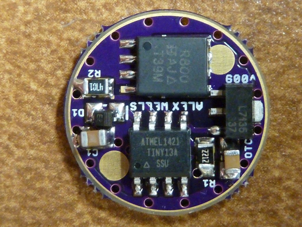
So I got my 17mm DD + single 7135 v009 from OSH the other day and noticed something: There is no exposed negative ring on the spring side—it’s all solder mask. The OSH picture (and pics in this thread) shows a ring there. There is only a thin ring exposed on the component side. Looks like I need to do a bunch of scraping or re-order.
Do you guys have a ground ring on the spring side?
My EE X6 triple is getting off to a bad start: The heat sinks are loose (and different widths) and will need to be $himmed, and my driver only has negative on the component side.
Thanks
Hi LED B... You got a similar problem to what I had - accept mine had the spring pad covered, yours has the grnd ring covered. Contact OSHPark support. In my case, they created a new set of 3 boards and sent them to me for no charge. I am still using the bad ones by scraping off the purple layer off the spring pad. I used a rounded edge exacto knife - works pretty good. I dunno why wight left a good portion of the grnd ring covered, may be a good reason..., but I usually scrape off the remainder of the covered grnd ring anyway, and also expand the spring pad by scraping it wider as well. It seems to be the covered portion of the grnd copper layer is slightly higher, so depends on where/how it's mounted if you make good contact or not.
I'm get'n pretty good at scrap'n  .
.
Hi Tom:
Trying to picture rounded edge blade. Off to Google I go.
I’ve had problems with too-small spring pads too. It’s either scrape, or scavenge a skinny spring off a 105C driver.
…But I do have a lighted stereo microscope, so these getting-old eyes can see what I’m scraping.
curved edge would be a better description I guess... It's not a straight line edge ..  Dunno - I got a set of them laying around, and think it's less likely to break a tip off by using the curved edge blade. Google "exacto curved edge" - a pic appears, and that's the one I use.
Oh doh! (Smacking my forehead) Ya, I can see where a curved blade would be better for scraping. Off to Michael’s for #21 or #22 blades.
I usually scrape the ground ring clear and flip the retaining over after drilling the grip holes all the way through. They put a bevel on the inside edge which limits contact with the ground ring, by flipping it over there is a wider area of brass to contact the driver for a better ground. ![]()
I kind of like the obvious gear change when going from Turbo to moon. It’s the system switching to the 7135 chip and turning off the FET.
And I do believe TK does NOT use the 7135 at 255, full on power is the mosfet only.
Next time you go to the dentist ask them for any old tools that they would otherwise throw out. These are designed to scrape plaque off of hard surfaces. I've been using them for years to scrape soldermask or paint, etc.