I am looking to get this light as well. Just not sure what is the beam range and spill area. Any owners have some beam shots of this light outdoors? TIA!
Bought and received this light. It is quite a long light and a bit heavy. Throws slightly better than a Ultrafire C12 with 8x7135, with a more intense hot spot.
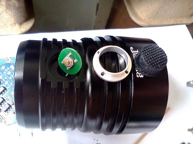
Curious about the internals, I proceeded to take it apart...
Composite picture below is from seller showing the different parts, as I did not take pictures during much of the dismantling process. Unscrewing the aluminium bezel will give access to the reflector, pill and LED itself. The insulating gasket is a bit high, and much of the LED lens is being blocked by the gasket.

The light switch is a press-to-on type. Waterproofing may hold for splashes but not sure if it will hold under water.
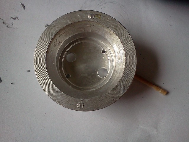
The LEDs lead wires need to be unsoldered before you can unscrew out the pill to access the driver. The pill is as below, with a shelf machined to fit a 20mm star nicely. The star is only held down with thermal paste by default but there are 2 smaller holes with screw threads, which you can add 2 small screws to hold down the star.
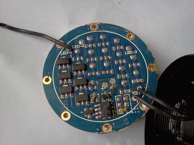
The driver is glued to the head by thermal glue. Giving it a few knocks with a wooden dowel will loosen it out. The driver can actually drive 3 LEDs but only 1 set of "circuit" is used to drive the single LED. There are 6x7135 (380mA), giving a total of 2280 mA. The first set of circuit can actually accommodate 7x7135s but mine only has 6....
Unfortunately, while attempting to mod the driver, I may have accidentally shorted something and I suspected I fried the IC at the bottom. The flashlight no longer lights up.
Now I have trouble trying to find a replacement driver of 40mm. The Skyrayking driver may fit in terms of diameter but the components are too high. The space between the driver and the pill is woefully small so those boards with components jutting out can't be used. Anyone knows of a 40mm driver which is rather "flat" like the original board? Or would it be better to try and piggy back another board onto it? Any recommendations for a good driver with electronic switch? TIA!
How about 40mm BLF FET driver from RMM? ![]()
http://www.mtnelectronics.com/opencart/index.php?route=product/product&path=67&product_id=276
but apparently it’s out of stock :~
That would be the board to get and/or the 12A 32*7135 board
It looks like a knockoff of this light.
I hope the parts and accessories are compatible.
Here's an updated JKK18.
here is a very detailed review of an authentic zerohour flashlight
 Flashlight review, by selfbuilt")
My Jkk18 uses a smaller driver board (about 26mm, guess there’s a removable ring, so driver could be around 24mm).
Was really happy, but unfortunately my jkk18 died after some minutes in highmode.
Obviously something which I can not identify at the driverboard is defect.
Does anyone know a replacement or better can identify the identification on his driverboard?
Couldnt find a sideswitch-driver, 3 mode, ~100/700/2.2-3A, yet.
http://www.bilder-upload.eu/show.php?file=cf78fe-1412689988.jpg
http://www.bilder-upload.eu/show.php?file=c6e75b-1412690029.jpg


Bubu, welcome to BLF! Thanks for sharing the info and pictures of the driver. You can use a DrJones driver or the STAR momentary switch driver that Mountain Electronics sells. There are other options too. When you buy from them, you might want to ask where the leads for the switch should be soldered. The old driver will serve only as a battery contact board with wires connected to the new driver that will float inside the pill.
Hi, thanks!
The pretended burned part at the driverboard seems to be ok, but I really thought it was the defective part. Although I cant read the description on it.
Fortunately my driver wasn’t the problem. The Led was (xml2 cw on aluminium 20mm star). At the connections of the Led current flows, but no light is visible.
Didnt make sure if there is a cooling-issue yet, but at first glance everything looks fine. Furthermore xml2 on ~2.1A (6*7135) shouldnt be a problem with that massive housing. Just bad luck? (There is a small pill behind the star which is plugged into the flashlighthead, also a small drop of thermalpaste).
Nevertheless I will look for an other option if my driver will die eventually. There is about 10mm to the led-mounting from the bottom of the drivermount. So I guess everything up to 7-8mm as replacement will fit inside - between dead driver and Led.
My JKK18 should be here in a couple days. I plan on reviewing it. Most likely it'll be a full review with some new testing tools, but it might just be a shorter review with typical BLF mods.
Hi,
banggood specified the flashlight with an additional candle-mode, but unfortunately this feature is missing.
It seems that banggood sells the same as kaidomain (the body differs from the BG pictures, its exactly like the new version from KD).
There’s a driver with 6 * 7135s and a preparation for a 7th. Can anyone tell me if I can add this candlemode ?
This light looks like just what I am looking for. Sure hope to see that review up soon!!
Mine has been sitting in a po box in another state for a couple weeks. Hopefully it'll get mailed to me next week.
Kaidomain now has the JKK18 for less than what I paid at Aliexpress.
http://www.kaidomain.com/product/details.S023692
$38.37
I think I am going to order this.
This is a great product. I am not so good at the reviews but I will tell you all that this device deserves more attention then it is getting. KD was fast to ship this and it is well built and exactly like described.
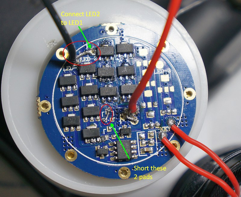
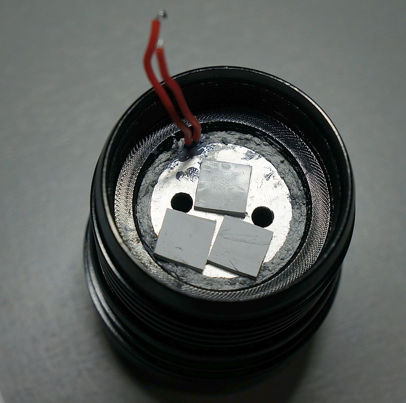
The JKK13 & JKK18 really do deserve more attention. With 3x18650 batteries in parallel and 1x XML2, run-time can really be extended, especially if you mod for high currents. I managed to buy two original JKK13 drivers as replacement for my burnt one and got down to mod the light. The large reflector of JKK13 should give plenty of throw.
The JKK13 driver can be used to power 3 LEDs in parellel through 3 banks of 7135 slots, however, only 1 bank with 6x7135 (380mA) is used since there is only one LED. The mod is therefore to fill up the 2nd bank with 7135s and join to the 1st bank in parallel for their respective outputs to be combined. The two areas circled in red needs to be connected to join the 2nd bank to the 1st bank. I used a total of 12x 380mA and 1x 350mA 7135s to give a theoretical output of 4.91A.
The stock LED star was also changed to a Maxtoch DTP star with XML2 U2 1A LED (stolen from my BLF X6! :p). The original position of the LED star sits too low in the reflector, with about a 2mm gap between the top surface of the star and the base of the reflector! ![]() I added another aluminum star (with resist layer sanded off) below the DTP star to raise it higher into the reflector.
I added another aluminum star (with resist layer sanded off) below the DTP star to raise it higher into the reflector.
Next is to boost the heat transfer pathway from the pill to the body. Added plenty of thermal paste to the screw threads of the pill and potted the gaps between the pill and the body.
Next is to test the current at the LED by connecting an ammeter between a LED lead and contact pad with thick gauge wires.

Below is what I got:
Low: 0.15A
Mid: 1.13A
High: 3.97A
Doing a spring bypass at the driver bumps the current higher
Low: 0.15A
Mid: 1.24A
High: 4.40A
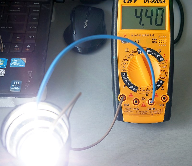
The output is now way higher than the stock light and the hotspot more intense and slightly tighter. Lits up objects 300m away with no problem. Sorry I don’t have a light meter so can’t measure Lux or throw.
Beamshot of ceiling. In real life, the rings are not that visible. Caused by excessive sanding of the centering gasket.
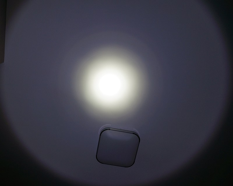
ISO 200, F5, –1eV
Compared with BLF X6 NW, both at highest. JKK13 at left, BLF X6 at right
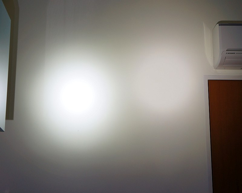
ISO 200, F5, –1eV
Underexposed shot to show the difference more clearly

ISO 200, F5, –2.7eV
I just modded my JKK13 to add a 17mm FET +7135 driver I won on a giveaway (Thanks Pilotdog68!) and a XP-L 1A V6 from LEDDNA the light is perfect now! the modes are as follows
0.1%……3
2% …….7
5%……13
15%….38
40%…102
63%…160
100%.255
It is using a variation of this driver he used
The FET +7135 driver does not fit in the space between the stock driver and the pill, so I had to do some extra steps. here we go
1.- Unscrew the side button switch and unsolder the 2 silicon wires and keep them handy (I reused them on the new driver)
2.- Unscrew the crown and remove the glass using a suction cup because it seems to be stuck to the oring that is stuck to the reflector
3.- Using a hook or tweezers carefully remove the silicon O-ring that wedges the reflector in place making sure it does not fall in or touch the reflector.
4.- Remove the reflector by gently tapping on the back of the light being careful not to touch the surface of the reflector store in a safe place along with the led centering ring.
5.- Unsolder the wires from the star and remove, clean underside of thermal gunk if you plan to reuse it
6.- Unscrew the aluminum pill using needle nose pliers and rotating counter-clock wise, clean and put aside for later use
7.- Gently tap the driver with a rubber mallet or other soft material, the driver is held down by glue it will fall out
Now you should have an empty host, clean all debris and oils from inside the host (But Not the reflector, duh!)
Since I planned to use the FET +7135 driver I had to make room for it to fit so I did the following
1.- Un-soldered all the components from the stock driver making sure you unsolder the spring and put away for later use.
2.- Used a metal punch to make a mark on the exact center of the driver on the spring side (Where the spring of the driver used to be)
3.- Drill a small hole through the stock driver using the smallest drill bit you can find, then proceed to enlarge the hole using bigger drill bits until you can fit a step drill to enlarge the hole until its about the size of the 17mm fet driver, I stopped at around 16 mm and proceeded to make a socket so the driver will not move, I had to finish using a dremel and later a file for finishing touches.
4.- Make sure that the new driver is sitting in the exact center of the old stock driver
5.- Now the driver sits inside the stock driver, I used epoxy putty to secure it in place.
After the epoxy cured I did
1.- Attach the stock spring to the new FET driver and used de-soldering braid from the tip of the spring to the center pad (+) of the driver
2.- Attach 20ga silicon wires for the leds to the FET driver
3.- Attach the stock silicon wires to the OTC pads making sure they do not get soldered or make contact to other parts of the FET driver
4.- I soldered 20ga ground wire from the stock driver to the ground of the FET driver
The driver is ready for installation
Now for the aluminum pill
1.- Clean and degrease the aluminum pill
2.- I used sand paper of 1000 grit and up to 2000 grit to polish the inside of the pill where the MPCB will sit,
3.- Find screws that will fit the original threaded holes the pill has, I found 2 that make a perfect fit from an old VCR I disassembled to salvage small screws.
4.- Put arctic silver 5 around the threads of the pill and at the base where it sits on the host and screw in tightly using needle nose pliers, make sure you torque it tight to ensure great heat transfer to the head of the flashlight
The pill is done, now for the driver
1.- Make sure the driver works before installing (Duh! H) )
2.- Cut to correct length (about 1/2 to 3/4 inch) the led wires and pre-solder them for easy install on the MPCB
3.- Put glue on the back of the driver and carefully install it from the back, make sure the silicon wires for the E-switch go through the side hole and the Led wires go through the proper holes
4.- Wait for the glue to cure
While I waited I did
1.- Solder the wires to the E-Switch and put silicon grease and reinstall the rubber booth.
2.- Lap the XP-L V6 16mm MPCB using 2000 grit sandpaper on a piece of flat glass make sure you do not put smudges on the dome!
3.- Pre solder the pads
4.- Make sure that the holding screws for the led you installed are at a good height for the led to slide in.
5.- Put a decent amount of Artic Silver 5 under the led and insert the MPCB to the pill making sure that the correct polarity matches the driver wires
6.- Carefully center the Led and tighten the screws to hold it in place
7.- Solder the wires to the led.
8.- Install the centering ring and reposition the MPCB if needed
9.- Install the reflector
10.- Install the silicon O-Ring
11.- Install the glass
12.- Install the crown
13.- Install the batteries
.
.
.
Pray that you did everything correctly ![]()
.
.
.
Press the button… 8)
Left is a Sunwayman D40A (XM-L2 U2) on turbo at around 1,000 lumens (Only stock light I own)
Right is the JKK-13 on turbo (XP-L V6 1A), it just blows it away definetly doing more than 1,000 lumens, on ceiling bounce is as bright as my modded TN-31
Pic is underexposed to show difference in brightness

Driver epoxied in place

Wow! A lot of work went into this one.
It’s always a good feeling when it turns out crazy bright.