Roche F6 hacking

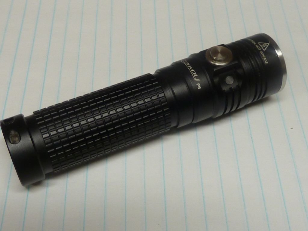
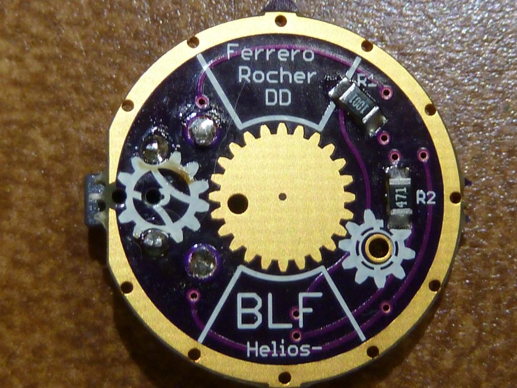
Ahh - got the Roche/Convoy F6 modded with the Ferrero-Rocher driver. Here's the detailed pics on the layout:

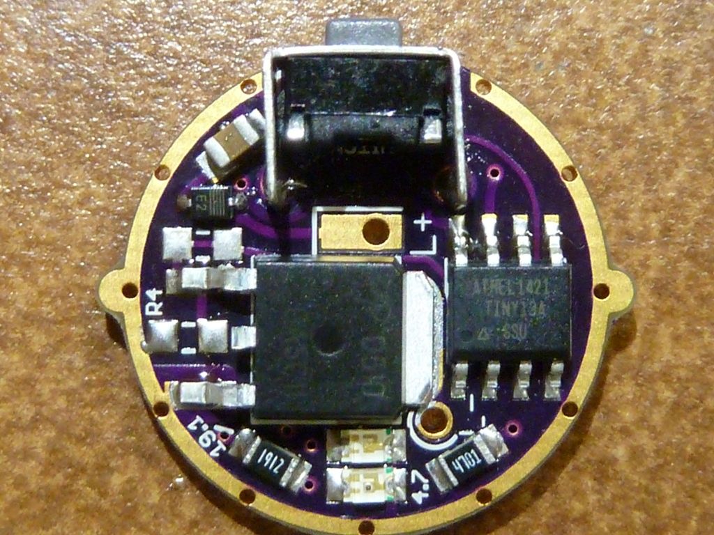
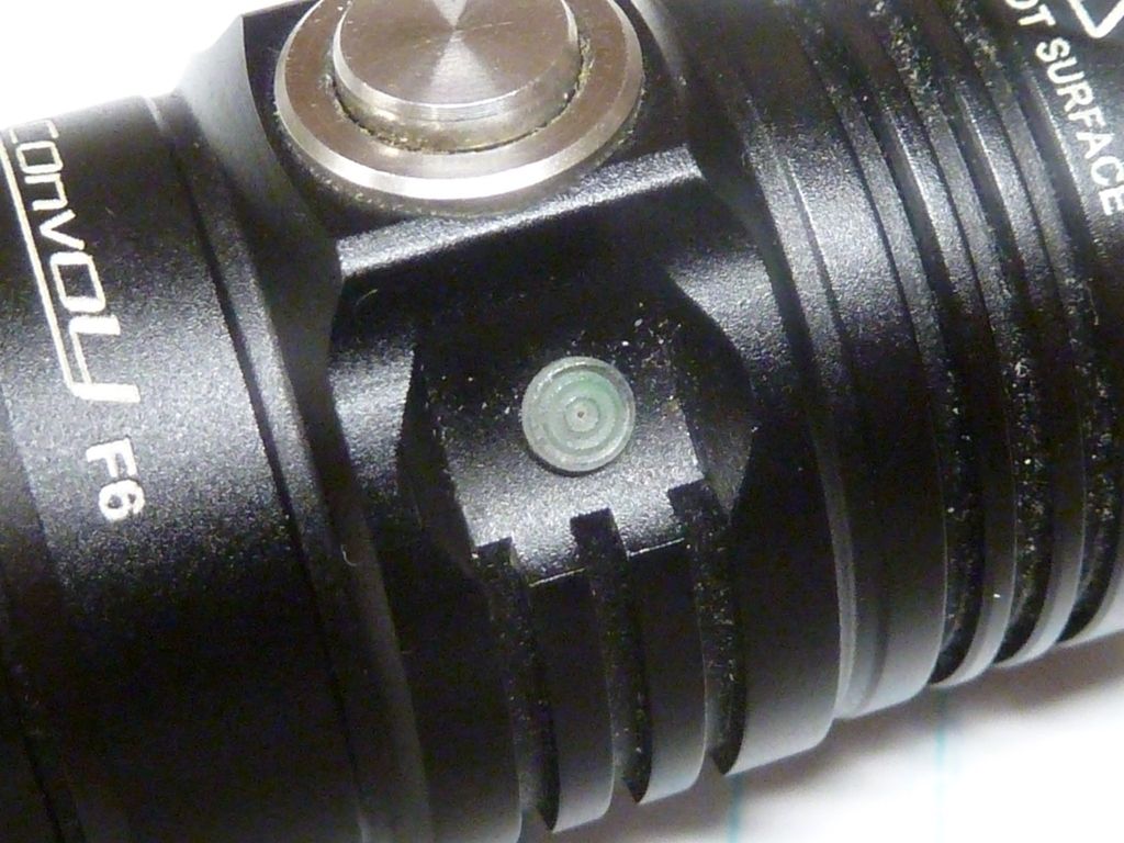
The color diodes are RED for R1/D1 and GREEN for R2/D2 (had to order it that way Smile). The RED D1 is below the GREEN D2 in the pic above. For the LED diodes, the green ends is for ground (Cathode -) -- this took an investigation for me to figure it out, because I didn't know for sure the green ends meant ground.

I used ToyKeeper's firmware for the Ferrero-Rocher as-is, accept for the modes - I changed them to 4 modes (PWN values: 1,20,80,255). Only thing I didn't check is the LVP: I'm getting 5 blinks when the cell is just below 4.20v, so not sure what's goin on -- should be 4 blinks.

The new Convoy F6, think it's same as 2nd generation Roche F6, has sort of a flaky button and I couldn't get it to work well with the switch chosen for this board. I filed down the PCB mounted switch button because it seemed to stick too far out, but the SS switch works really, really roughly. So after sanding down to maybe less than 1/2 the original size, and using some Teflon based oil, I was able to mount the driver but the feel is pretty awful, but t does work, and seems reliable at that. Weird because you really can't feel a "click" like you can with the stock driver. Again, not sure what the history was, but maybe it's more a problem or change with the 2nd (cheaper) generation.

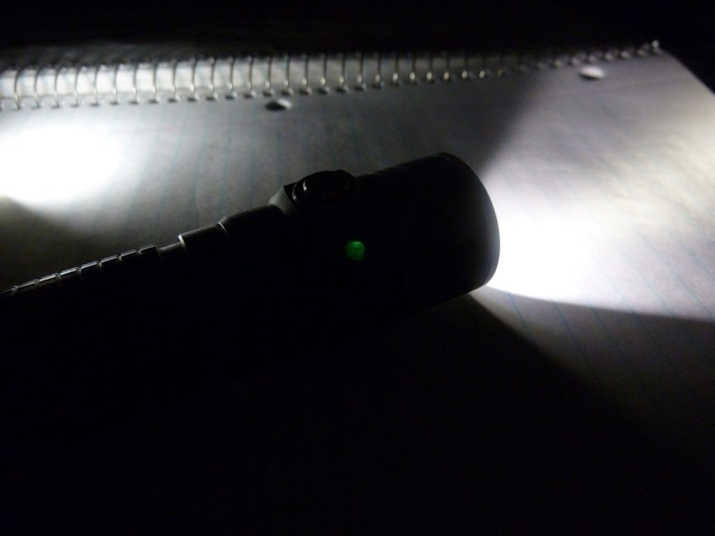
For the color LED's, well.... They do work, but the RED isn't so bright. I used the higher resistor on the RED and it's noticeably weaker. I drilled a small hole using a #56 bit next to the button where it dips in in order the see the light from the LED's. I can barely make out the GREEN and can't see the RED at all. The driver was laid out for the LED's to be opposite the switch, but for me, I'd rather see the LED's next to the button because you naturally hold a side switch light with the switch up. Well, it was an experiment anyway, so I'll have to look into what material would be the best to fill in a larger drilled hole that can pass light effectively -- most likely on the flat side opposite the switch. I know there was a couple of posts on this mod to an F6 somewhere, maybe earlier in this thread? Not sure... Think someone recommended light tube material but the ref. link was very expensive.

Note above, the switch is really close to the MCU but I didn't realize that, so had to program it after full assembly - was able to get the clip over the MCU and it actually did work on my cheaper black clip setup, not the more pricey blue clip from DigiKey.

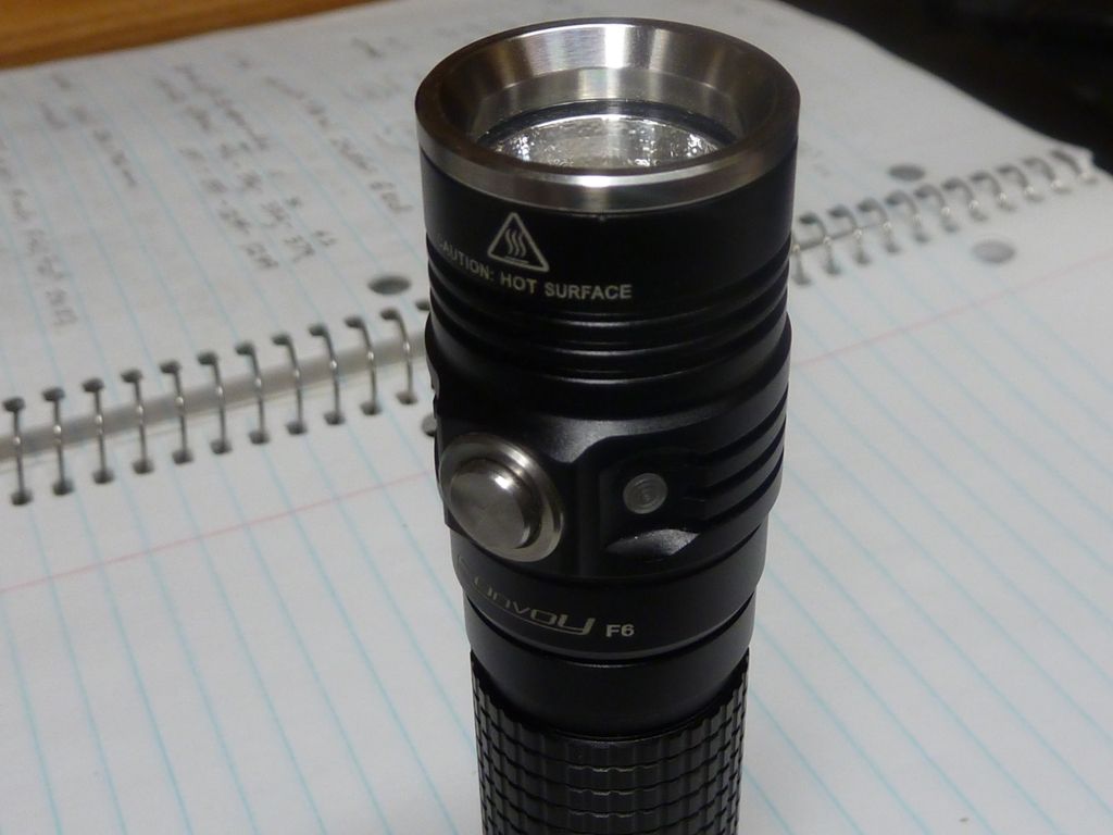
The beam and tint look great using an XM-L2 T5 5D3 (from Richard). The T4-5B1 was my previous favorite tint, but really like the nice warm white look of the 5D3 - no hint of yellow I can see - maybe the small OP reflector helps with that. I measured 4.7A at the tail but am getting only 840 lumens @start, 830 lumens at 30 secs. This isn't much better than what I got with the stock driver with 3.0A at the tail (after resistor mods), which was 775 lumens @30 secs. I didn't bypass the driver spring, but do have the tailcap spring bypassed. The low droppage in the 1st 30 secs is a sure sign of resistance being in the path. Note in the first 10 secs, the output actually rose. I can hopefully fix that when I tear it apart again for the LED viewing problem. Also will replace the lens with a UCL. Stock lens is 24.0 x 1.45 mm and the UCL that should fit ok is 22.61 x 1.86 mm.

I love these things. :slight_smile:

It seems a little weird that you’re getting only 840 lumens at that power level.

As for the red being dimmer, I think comfychair changed the resistor values after he built mine. The first rev produced pretty equal brightness for both LEDs when viewed directly… but when viewed through the window the red overpowered the green. With both on, it looked orange instead of yellow.

The status LEDs also change brightness depending on whether the light is on. They’re much brighter while on, and rest in a rather dim state while the main emitter is off. This brightness isn’t easy to soft-tweak though, since they only have three states (high, low, off).

In any case, I see a few differences on my driver:

  • The pads to the upper left of the FET are bridged.
  • The component between the FET and the cap (next to the switch) says “41” instead of “E2”.
  • On the spring side, R1 and R2 are values of 471 and 102 instead of 1001 and 471.

I buzzed out things and didn't see a reason to bridge those pads - I'll check again - you might have something there.

Resistors marked 102 and 1001 should be the same, I think - if I understand the markings correctly. The last digit is the # of zeroes to add.

Also, the diode marked 41 should be the same as E2 - I got the E2 from Richard, while the 41's come from DigiKey. I was short diodes at one time, and Richard added some to my order.

Have you worked with the Rev 2 Roche? I know you have one you love, but think it's a Rev 1 Nichia triple that does 1800 lumens, from what I recall. I don't recall any posted details on how you built it though - what did you use as a spacer?

I haven’t worked on the hardware for a Roche. Comfychair built this one and sent it to me because he wanted firmware written (so it’s his fault we have code to run on it). I think the build details are back a few pages in this thread.

If the 1001 is the same as a 102 and E2 is the same as 41, then the only difference is that your 1001 and 471 are swapped compared to mine. I’m not sure what effect this would have. Er, and I have two pads bridged where yours aren’t.

Just looking at the driver, it’s going to be very difficult to see the indicator LEDs from the switch side of the body. There’s a big FET and thick wire in the way, blocking line of sight.

A little while ago someone asked me how the size of SMD LEDs compares to Cree LEDs, so I sent them this pic of the Ferrero Rocher driver next to a de-domed XP-G2. Normally, the viewing window is toward the right edge of the driver as pictured, while the switch is to the far left. That FET and wire do a great job blocking the light:

The 1001 and 471 resistor are for the RED and GREEN LED's. According to Halo above, he said the RED should get the higher resistor (the 1K), so that's how I have it. If it's reversed from yours, could be the tweaking comfy did, dunno. They control how bright the LED's would be.

Found the loss of lumens problem! I was taking tailcap readings, so had a huge drop from the tailcap. The totally crappy tailcap spring they use looks like pure steel - no coating at all - impossible to solder to it. My cheap $10 ZY-T11 UltraFire clones have better springs in the tail. For the bypass, I wrapped the wire around the spring on top, then soldered it. On the bottom, just tried to jam it in but didn't stay. So I re-jammed it and the output is now much more respectable - 1,112 lumens @30 secs Smile.

Also, I had some intermittent issues that were solved by a couple of solder blobs on the driver ground ring, so it makes better contact to the brass retaining ring (the stock driver has the same thing -- should have known...). I also added the driver spring bypass. This helped a little, but the lions share of gain was from re-positioning the bypass wire on the tail spring.

That R3 pad, just above the top FET leg in the pic, actually has a trace connecting the 2 pads, so effectively it's jumpered.

No prob - was hoping someone who has would chime in. comfy's threads are almost worthless now without pics - he had some great detail in his pics, specially the ones with all the markups. I read the posts, and without the pics, it's some strange reading... He can be very brief at times Smile.

I really like this F6 - exc. quality, good heat sinking for such a small body, exc. SS trim, lockout feature, etc. The button issue is improving somewhat with usage, I suppose, or I'm getting more used to it (not smooth action, not always getting a click). It's worth putting more time in to. I gotta come up with a better fix for the tail spring, and the loose SS end cap.

The little hole I drilled for the light is really not so bad. I can even see the low setting green "glow" at night coming out the hole. Thinking I can improve on it as follows:

  • increase the hole size, maybe fill in with thin layer of clear silicone
  • tweak up the output of the RED & GREEN LED's by playing with resistor values (lowering)
  • maybe strip the black anodizing from the inside of the pill to get more reflected light - I believe the only way I'm seeing light from the hole now is through reflections

Other issue I need to research is the firmware's battery status check using main LED blinks - alwasy showing 5 blinks (max). Think something is broken there. When I had the driver on the bench, the RED LED did work fine for low voltage, so maybe some compile issue/bug with the on demand blinks. I'll have to re-check things - could be almost anything in the LVP path - hardware, etc.

There’s always the battcheck firmware if you want to get exact values. Especially if you have a bench power supply and DMM, it should be pretty easy to calibrate everything.

To see the status easier from the switch side, it might also help to put something like a glass elbow directly onto the LEDs to curve the light toward the direction you need it.

Hey guys,

is there a firmware similar to ferrero rocher but with mode memory(like baton or others)?

I wrote my own firmware but without the nice ramping and voltage monitoring@long-short klick(ferrero rocher) and also without WDT,
so its actually only usable for Bike Lights…

Thanks a lot! :slight_smile:

If I understand correctly, you could use Baton.c (in the same directory as Ferrero Rocher)… It won’t remember the mode if you remove the battery, but otherwise I think it might do what you described.

Or Ramping_UI_table.c has memory too, but uses a smooth ramp instead of a stepped ramp. Again, it forgets when the battery is removed.

Not that kind. Ferrero rocher did not have a click to off option like baton code, this is what I mean. While in on mode, click or long click to go to off, but save current mode so it can be set by next short click from off mode, as baton does.

That the mode is not saved when battery is turned out is clear, as there is no eeprom saving in baton or Ferrero rocher.

I think I may be a little confused.

Ferrero Rocher by itself does not have click-to-off, but both Baton.c and Ramping_UI_table.c do. A single short click turns them on or off, using the last-used mode.

If you want click-to-off in the Ferrero Rocher interface, you might want to take a look at Tom_E/eswitch.c. It switches short click from “next mode” to “off” after the light has been on for 1.2 seconds.

Is this closer to what you want?

Accept my version doesn't have memory, but you could use the mode switching timeout method from it Smile. With quick access to lowest, and quick access to highest, I never saw the need for mode memory with this e-switch firmware.

ok guys, it seems to be difficult :wink:

So i will try it that way, like toykeepers baton and ferrero rocher:

From off:

- Short press to enter last mode.

  • Very Long press to enter the lowest level.
  • Long-then-short press to display battery status and then shut off.

While on:

- Short press to increase brightness level. Keep holding to step up to
higher levels, and release when the desired level is reached.

  • Long press to shut off(save last mode).

I got my 1st Roche F6 up and running quite well now/ Solved the loose end cap problem and added a light pipe next to the switch. Here's some pics:

The light pipe installed is here: http://www.digikey.com/product-detail/en/0/LMC_040_CTP-ND

I'm lefty so preferred having it to the right of the switch because I hold the light switch up in my left hand, usually.

The tailcap was loose, so I jammed in several layers of alum foil (Heavy Duty), and jammed the cap down, trimmed the foil back - might still notice slight fragments of it sticking out of the joints. I don't trust it with the striker screwed in though - might not hold up under heavy twisting or blunt force trauma.

Oh man…that light pipe (acrylic rod) is AWESOME!

What firmware you running on that (disregard, post #211 explains it)…very cool build!

Might try some loctite red (271) on it…let it dry and it acts almost like an adhesive…will take heat to break it loose the next time

Or you could just epoxy it in…but it would be permanent then

FWIW, I’m planning a ramping FET+1 firmware soon. The upside is better low/med modes, but the downside is that there aren’t enough attiny pins to support red+green LEDs, an e-switch, LVP, and a second power channel. It’s one pin short unless you use pin 1 (which would mean no reflashing afterward).

Yes - it's pretty much the stock T_K firmware. The light pipe is a tight snug fit with no adhesive so far - probably should use something though for water resistance, but think it must dry clear. I had to cut it down to fit, using a cut-off wheel on my rotary tool. It somewhat melted the plastic, but no ill effects.

Ohh - dont' think I posted this, but on about July 5th I did the repair of the tailcap - took 2 strips of heavy duty alum foil, folded them over to 4x times, jammed them in to get the SS tail cap to hold. I also re-soldered the tail spring bypass so I good a good connection there. Results were:

On a fresh AWT IMR 2500 mAh cell @4.20v, 5.35A @tail and 1394 lumens @start, 1285 @30 secs on the T5 5D3 XM-L2/Noctigon.

Not bad for this light - the SS bezel is quite deep so I think it blocks a little output

Anyone else see these?

http://www.aliexpress.com/item/Compatible-tube-adapter-m18650-14500-16340-tube-hard-oxygen/1908125904.html?spm=2114.01020208.3.20.LI5YBO&ws_ab_test=201407_5,201444_5_3_2_1_5_4,201409_5

Looks like they got the 14500 tube - hope it would fit the F6, think it would, not sure. Think'n of ordering one. They also have the screw in accessories, pricey a bit though.

This buckle looks nice too: http://www.aliexpress.com/store/product/Cnc-304-stainless-steel-ultra-hard-series-flashlight/505693_1608581980.html