06/17/15 - My build has come to a halt. I think it will be at least 2-3 weeks before I progress. I ordered a 48v fan, but it has not shipped, so now I have to play the ebay wait game, to get a refund and start all over again. I also had to send out the heat sink to have someone machine fins in it, so the project is just shut down for now.
Hello,
I am at it again with another handmade light.

This will be another hand made light using aluminum parts from Speedymetals. The led will be a Cree CXA3590 and the reflector will be the Illuminations Machines LUM 5-90. The video above describes what the build will be and uses bunches of useless information, so I can wander on and on aimlessly.
The photos show some of the components shown in the video and then the build begins... at the end... of them.

Cree CXA3590, still on the way from This Seller.

All the aluminum comes from Speedymetals. They do small runs and cut that way I want. The rectangular tubing above, will be the body, housing the batteries and the 600 watt DC-DC boost converter.
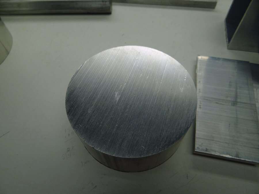
The heat sink is a chunk of 3-3/4" aluminum rod stock that is 2" thick.
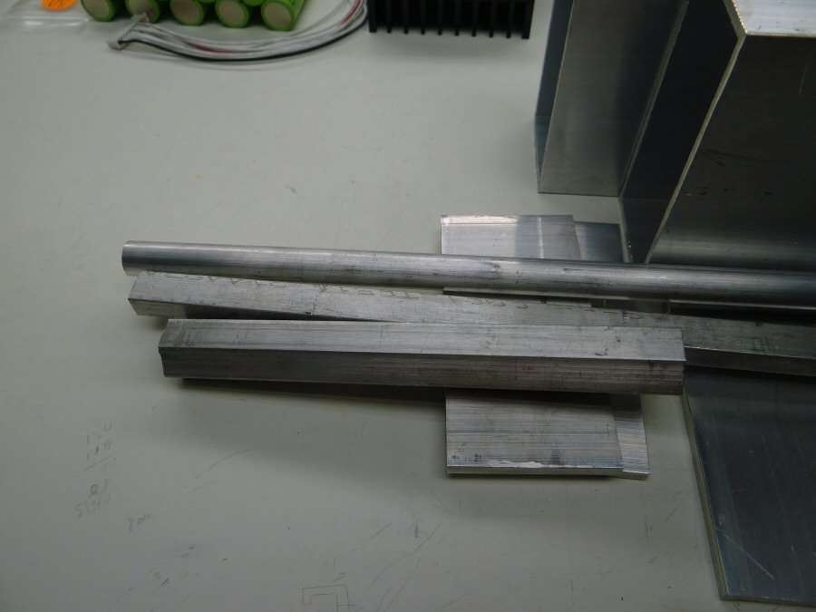
The handle will be out of hex rod.
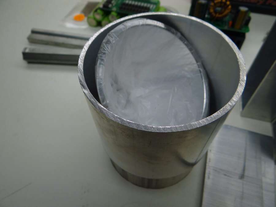
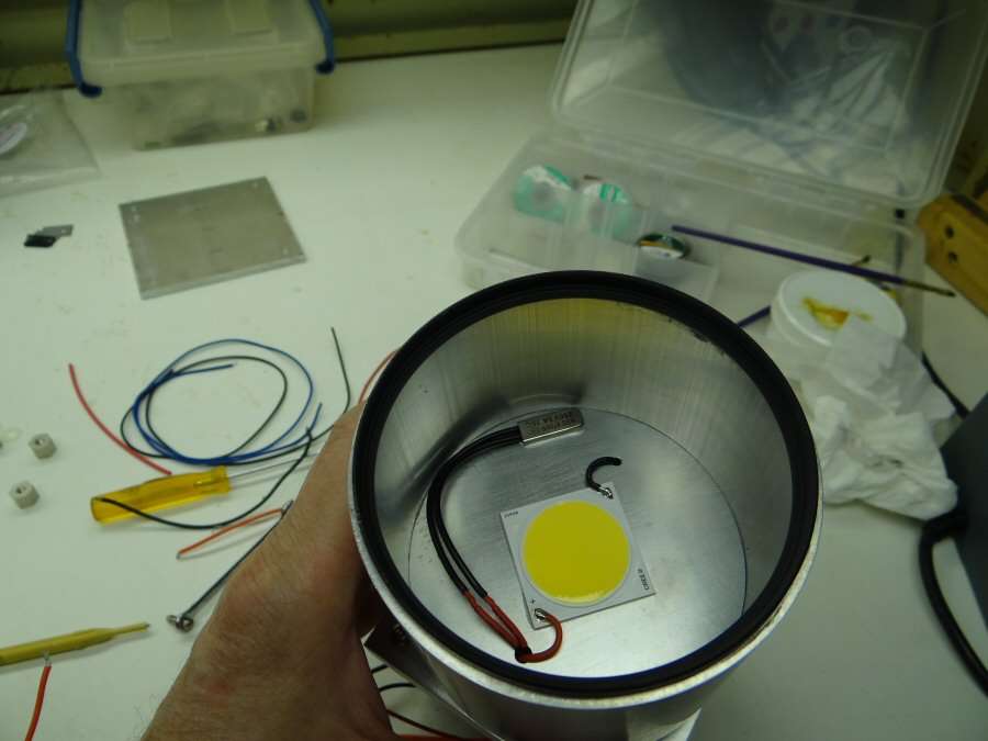
The LUM 5-90 reflector and the UV filter will be in the Aluminum tube head.

The amp/volt digital display came from ebay. It should be able to handle the high voltage.

All the other misc items came from ebay. Aluminum hinges, Clasps and charger plugs.
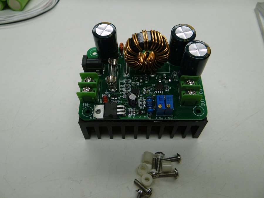
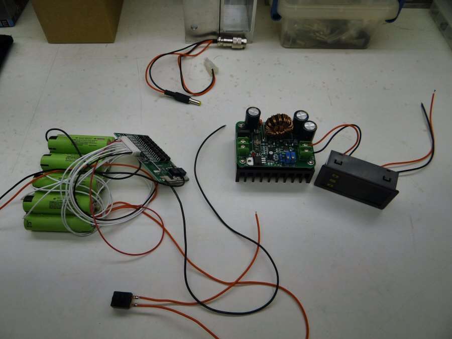
The 600 watt converter is a first for me and I hope it works. It has trim pots for voltage and amperage. I plan on using them for adjusting the light output, from the outside of the case, for a kind of step-less brightness control.

I need 36+ volts to the led, so I thought I would try to provide close to that voltage, to the converter, by using 9 Li-ions in series. I am also going to use a PCM for balancing the cells.
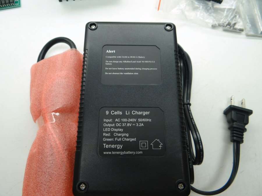
The charger comes from All-battery too.
------------------------------------------------------------------------------------------------------------
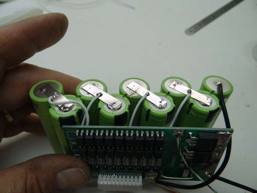
Ok, so what I have done so far, is to make the battery pack. I am using 9 Panasonic 18650PF cells. I am running them in series and the first thing was to make them into a pack that would fit in the aluminum tube that I selected.
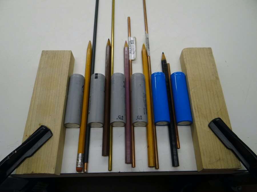
I wanted them to be seperated a little, to keep the overall height low, so I used this "fixture" to set up the base for the cell pattern. I used about anything I had laying around, to make the spacing I wanted. Older cells were used for the bottom pattern layer.

Then I just added the 9 cells to the fixture and glued them together.

I used Epoxy, because I didn't want any flex. These cells were hard to glue. I had to use 220 grit sandpaper on the wrappers, to get them rough enough for the epoxy to stick to them, but it worked. Next will be soldering all the balancing leads and tabs on.
That's it for the moment. More, when I get more - 06/04/2015
---------------------------------------------------------------------------------------------------------------
06/05/15 Not too much to post. Lots of other things to do, like looking for a job and dealing with the unemployment people, but I did spend a little time in the garage. It's hot now. In the 90's in the garage, so not a lot of time spent. I did manage to wire up the PCM to the pack.
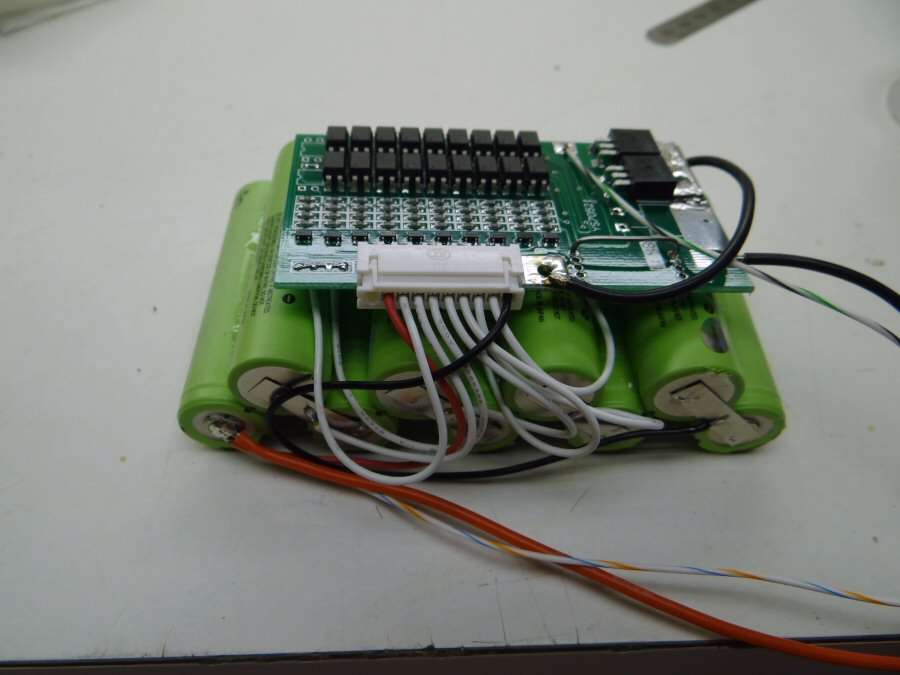
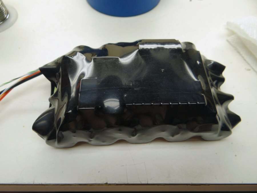
I had to snip all of the tiny component pins sticking through the board and then I sanded the ends, so they were not sharp. I used some layers of tape over them, so they wouldn't poke into the battery sleeves. They were sticking up too much and I don't really want a short. The outer wrap looks like hell, but I'm not all that good with that stuff. It holds everything together and it will be hidden in the light, so it will have to do. I don't have any more of that size sleeve, to try again. Tonight I will try out the charger and see if the board is working right. Funny, I always wait to check until I have closed things up and then I have to undo all of it. I'm so one tracked, someone could walk up, holler at me and hit me over the head, before I ever stopped what I was doing.
------------------------------------------------------------------------------------------------
06/10/15 - The leds came in finally. They were packaged well. Just like they came from Digikey or Mouser.
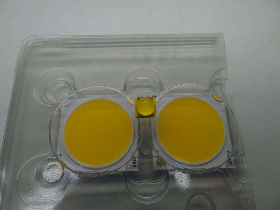
The MT-G2 looks a little puny when it's up against these guys. Oh, if you are curious about the back side of these, it's just the plain ceramic backing. The contacts are on the front corners. I will just be using AA thermal adhesive to hold the led onto the heat sink.
I figured I would give a plug to the guy who I dealt with in China.
Hopefully, I will be able to do some testing this week-end. I will hook up two meters to the DC-DC converter and see what I can get for volts and amps, while hooked up to one of these. Yep, I ordered two, just in case. If one is still left over, I will just have to find something to toss it into.
-----------------------------------------------------------------------------------------
06/11/15
http://www.youtube.com/embed/vYNebuvk3dM
Video part 2. Testing the monster!
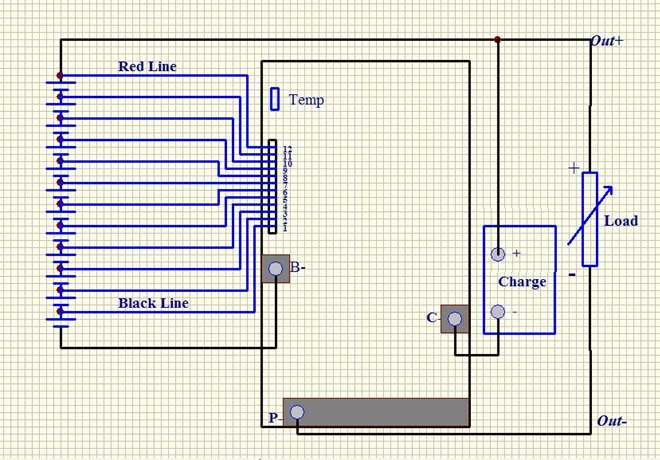
The wiring diagram below shows how the PCB is wired. The video goes into a lot more detail. It was the most wiring I have ever done for a light and I was just a little nervous.
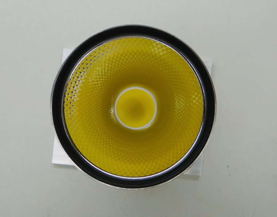
The led is mounted, wired and the reflector has been opened up to fit over the led.
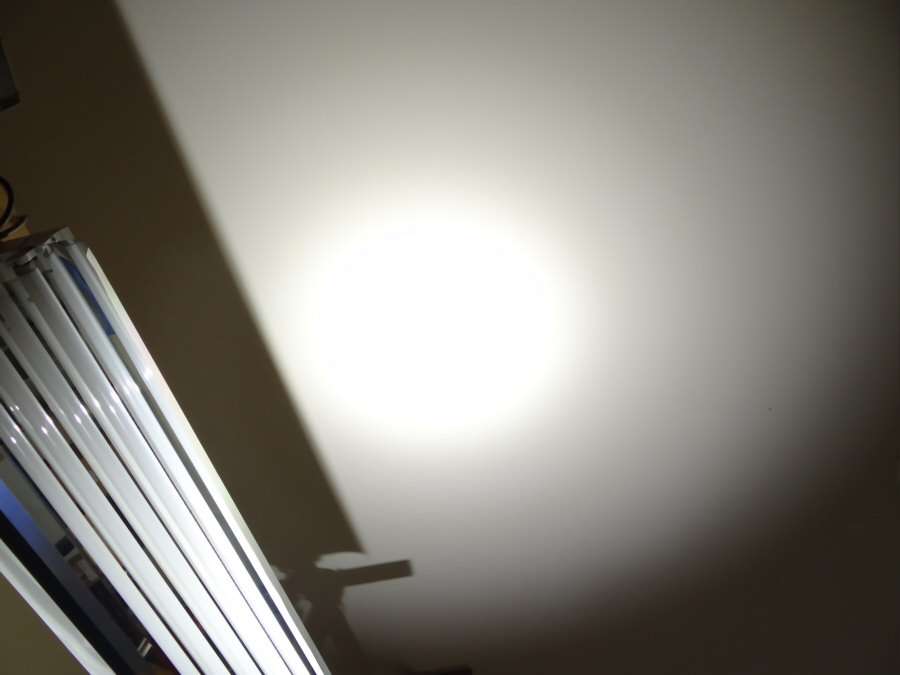
I am not ready for actual beam shots yet, but here's a taste. This is at ISO 100 and 1/250th of a second shutter speed.
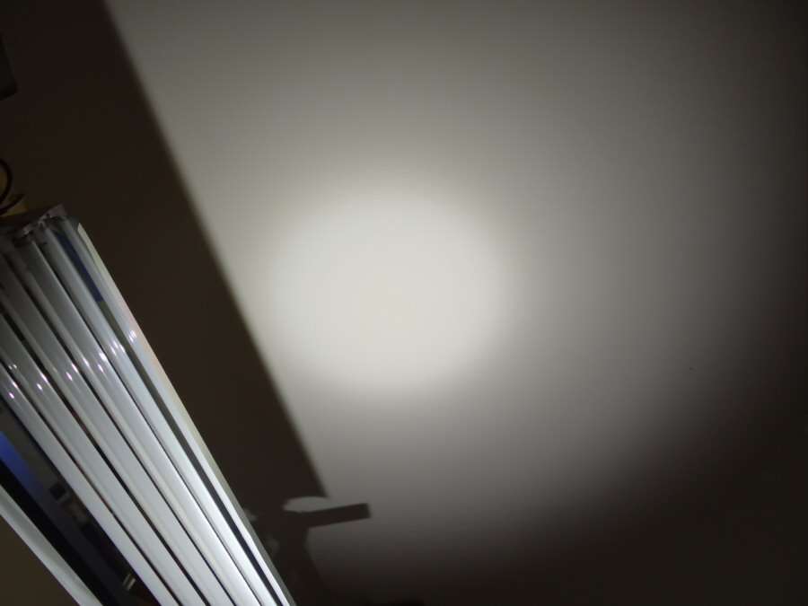
I also did it at 1/500 of a second, to see the spot in more detail. It's large, but not near as large as I thought and it's smooth as can be. This is at 6 feet away.
I ended up at 45 volts and 4.25 amps. It could go higher, but I don't think I will play any more. That's what? About 190 watts? Well, that big heat sink gets so hot, so fast, that I couldn't touch it right after the testing.
More when I get more.
----------------------------------------------------------------------------------------------------------
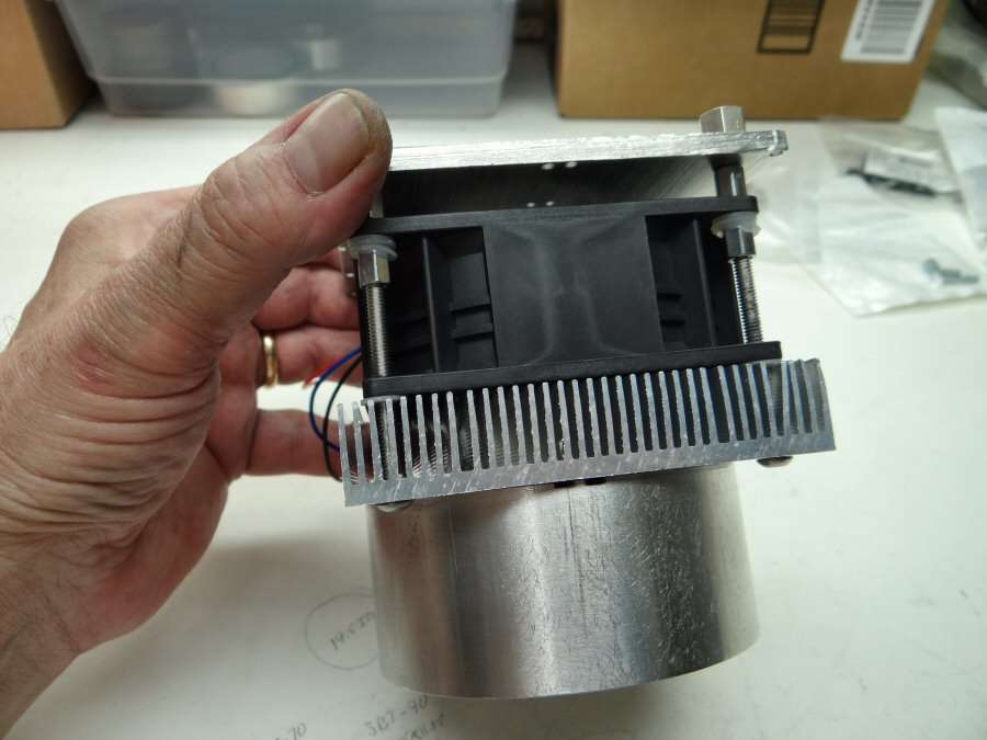
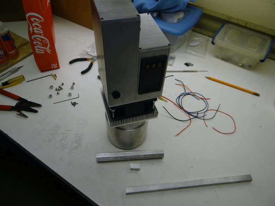
07/07/15 - A Heat sink came in, so I have been working on making some progress tonight.
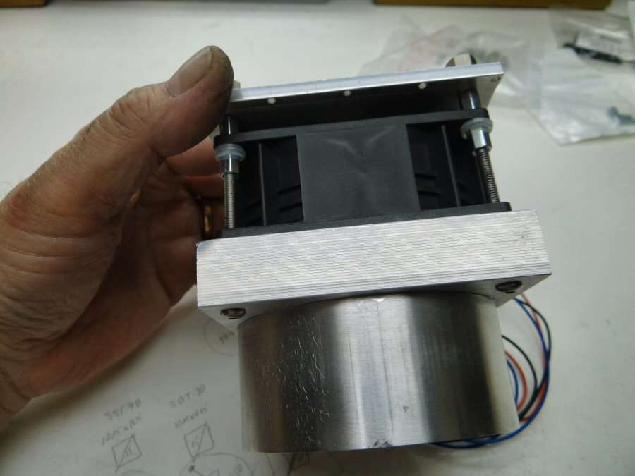
So, I bought a 100mm x 100mm finned heat sink off ebay. I mounted it to the back of the big round heat sink with a bunch of #4-40 screws and used thermal adhesive between the two. Then I put 4 bolts through the finned heat sink, throught the fan and into the back plate of the body. Those are #8-32 bolts. Evertyhing is spaced out, so there is nothing binding and there should be enough room for intake air flow.
I also ordered a temp sensor, so the fan will not turn on till the temp is over 105C. I still have to do a lot more work. Mount the temp sensor, mount a new LED. Yep, I ruined the one already mounted.
 Then I have to assemble all this for real and test it out again.

Here's an idea of how it will all go together. As I said, a lot still to do, but I am determined to get these lights done in a week or so. I hope to have beam shots of this one by the week-end. Hope, but not sure.
--------------------------------------------------------------------------------------
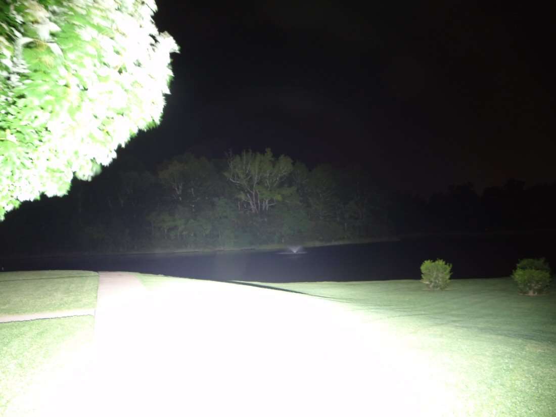
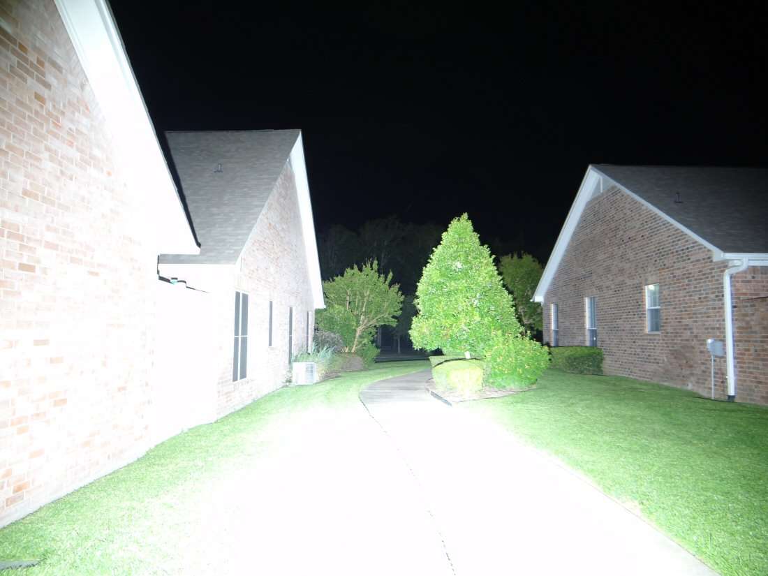
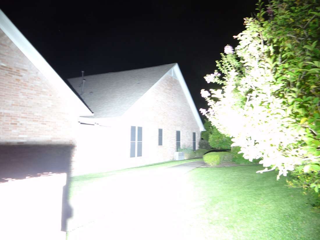
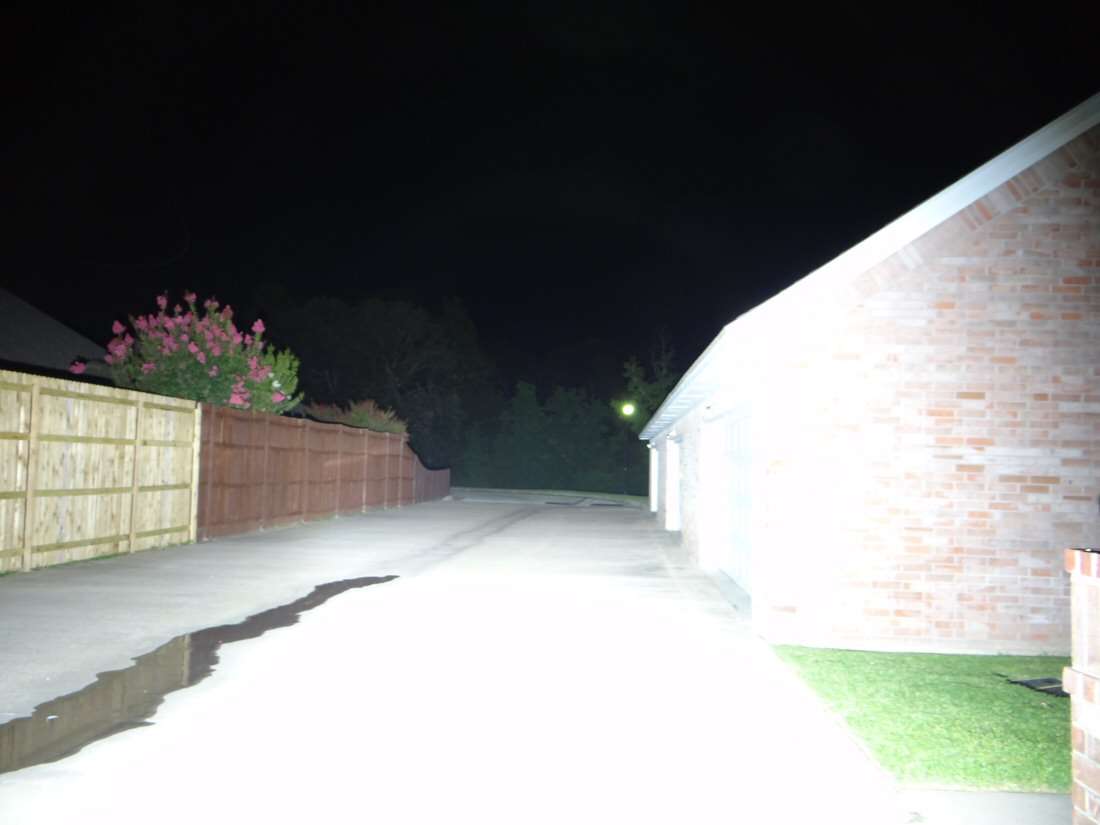
07/07/15 - Just about finished. All I need is to put the handle on and this thing is done! I will be doing beam shots tonight. I don't need a handle to do that.
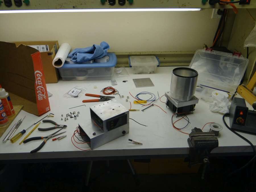
The shop is not always clean and tidy. I just don't show it in photos. Lots and lots of wiring on this thing, as well as drilling and tapping. It's good to get something together to where it's in running condition.

The guts are all back in the body. Battery pack with the charging control board. DC/DC converter, on/off switch and charging port.
I added a temp sensor for the fan. It will turn the fan on at 75C. I said 105C before, but it's 75C. The second led is in place and everything is wired up.
I was working on the handle, but I decided to come inside. It's close to 100 degrees in the garage and it's just not very nice. I can finish the light off in the morning, but I will do beam shots tonight. The idea of controlling the brightness didn't fare well, so it's a one shot light. On or Off. 44.5 volts @ 4.05 amps and I'm gonna leave it there.
I drilled hmmmmm, let's see, about 65 holes all together and tapped most of them. Lots of wire and lots of patience. Hard to do that for me. My patience is not what it used to be.
----------------------------------------------------------------------------------------