Yes you are right, i know that it could reflect as artifact but maybe there is a way around this.
And maybe the gain in output would be enough to be worth the possible artifacts, and at long distances maybe they wouldn’t even be visible.
What if the angle of the reflective surface would be slightly lower from the die edge down to the edge of the RA, shouldn’t that make the light be captured inside the RA to be recycled, so much less escapes beside the die as artifacts.
But i maybe thinking about this all wrong, it could be that to focus the RA properly you have to raise it higher than the die instead of lowering it, or maybe it could alter the process of focusing the RA completely, if one would be using an reflective surface at the bottom of the RA.
If you focus the RA properly, there shouldn’t be a significant amount of light hitting the MCPCB, the pill, or any other surface. The RA’s purpose is exactly to recycle the light back to the die that might otherwise hit one of those surfaces. The lens is the only other surface that light should be hitting, ideally. Everything else is waste. Even if normal spill is useful sometimes, it is still considered waste when figuring lux, throw, etc.
Yeah i know that the better focused the RA gets the more light gets to the emitter, but because a perfect RA probably is hard to do, maybe there can be gains from reflecting back that light in to the RA from the bottom that gets lost on the way, because it hits at the wrong angle in the opening of the RA.
Just like MEM found that several lenses ups the throw even when it shouldn’t just because of the imperfections in the lenses become less of a factor when it is shared over several.
You may be able to get some gains by bouncing scattered light back into the RA but I don’t think it’s going to be possible without introducing more beam artefacts at the same time.
I’d say there’s other places when you’ll be able to make more significant gains before that approach would be required. Mainly perfecting the geometry, polish and focus of the RA itself, that will definitely show the big gains first.
On that topic I’ve been playing with my melon ballers again
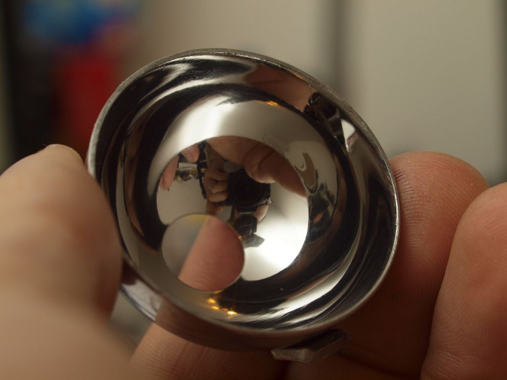
Had some time to do a better polish job on the stainless steel collar and am now working on fine tuning the focus. I’m pretty happy with the finish quality, there’s still some deeper “lines” that I wasn’t able to remove completely without starting over with progressively finer and paper but it’s probably as close to a mirror finish that I’ll be able to achieve with the tools I have here.
Not bad for a 4 dollar part at all, very pleased with it in fact. And it get’s noticeable less hot now so my light recycling efficiency has definitely gone up some.
Process was as follows in case anyone is interested.
1. Brown polishing compound on a felt pad bit spun in a basic cordless drill. Lots of pressure and drill set to high speed.
2. Blue polishing compound on a different felt bit.
3. Hand polishing using Mothers Mag&Aluminium polishing compound on a microfibre cloth. Again lots of pressure to really bring out the shine.
4. Finally I used some Vienna Lime powder to soak up and remove any remnants of the polishing compounds. Very satisfying step as the mirror finish comes to light
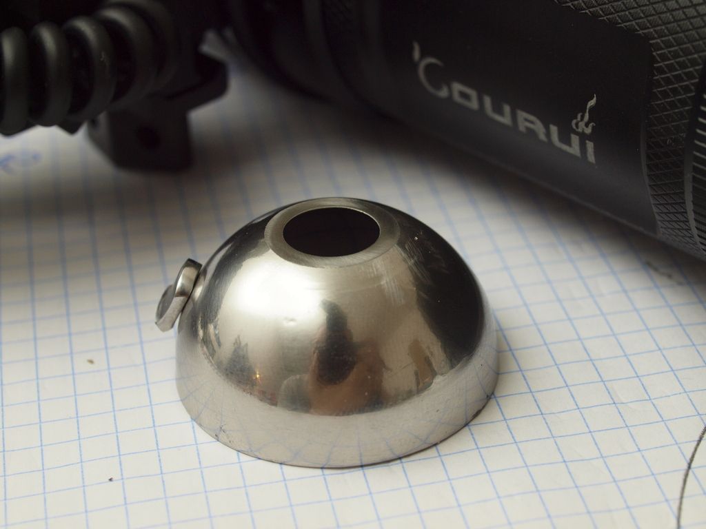
I also sanded the opening of the collar flat to remove the circular artefact that was visible around the hotspot. I actually noticed that I need to open the hole a bit more to ensure I don’t cut off light at the edges of the lens, at the moment I’m seeing 25% improvements without trying too hard with the focus of the collar. But I’m hoping for a bit more with the aperture opened up to fully cover the lens edge to edge. Not sure how much I’m losing here at the moment but I can clearly see that the edges of the collar opening starts partially obscuring the led before reaching the edges of the lens, that’s obviously not helping.
If all goes well I’m optimistically hoping for an end gain of about 30% with this particular collar. We’ll see.
Looks very shiny, i like to use an ultrasound washer to get stuff really clean, if you have access to one maybe test that to get an even higher shine, but maybe the Vienna Lime powder is enough.
You have obviously done your research on this & i haven’t yet, so it was interesting to know some of the steps required.
I hope i can find a cheap similar RA that will fit the smaller 1504
The lime is pretty spectacular in removing the waxy/greasy residues. Works way better than trying to clean it with say a microfibre cloth or alcohol swabs, it’s quite impressive. I’m sure an ultrasonic cleaner would do an even better job, don’t have one though.
I don’t know much about polishing but I ordered a kit on ebay and had a go, it’s fairly labour intensive and can be a bit frustrating at first but it’s really satisfying when it starts producing good results.
I think for the second cup I’ll take it right back with various fine sand paper to remove the faint scratches before polishing, see if I can get any improvements that way.
I haven’t torn apart a 1504 yet so don’t know the max size that would fit. Have you looked at other melon ballers that might work? Or tested other approaches?
I haven’t gotten mine yet, i got the shipping notice today, so i will wait before i get it to make some measurements, so i know what room i have to work with. But i think it is narrow, because the mcpcb is only 16mm for such a big lens light.
Have you thought of trying to find some small meniscus lenses to use as the first stage like MEM does? If i haven’t missed something vital i think he uses
LED>AR>meniscus lens>aspheric lens>and optional even bigger meniscus lens. And all the steps sounds like it has an additive effect on throw, i mean you don’t need all but the more of them you use the more throw you gain.
But still the biggest problem with that approach is it think you need, a very good handle on the underlying calculated values of lenses needed.
And so far that aspect eludes me
I don’t think I’ll pursue the additional lenses at this stage.
I was playing around with some simulations to figure out what’s what. Very useful to get a better idea of the calculations and relationships involved.
I think I have a decent idea of what I could do with a second lens but they’re relatively expensive things to play around with and I’m not really sure it’s worth the hassle.
I’m more interested in focusing on the diy collar stuff at the moment since they’re pretty straight forward to implement and gains are pretty large.
Also all this mucking about with throwers has give me an itch to build something floody again so I’ll probably focus on something like that soon.
I believe your dome is way way off center Linus. I put an SBT-70 under a dome I made, and there is nothing lit outside of the die. When you tilt a circle you get an oval. I see a big oval. So it looks like you’re either high or low, and tilted with the aperture. Find the high side, and remove metal.
Not sure which image you’re looking at to come to that conclusion.
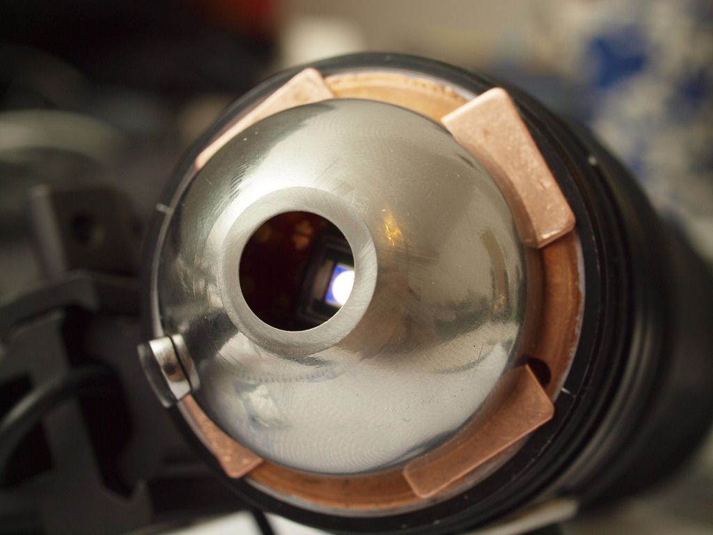
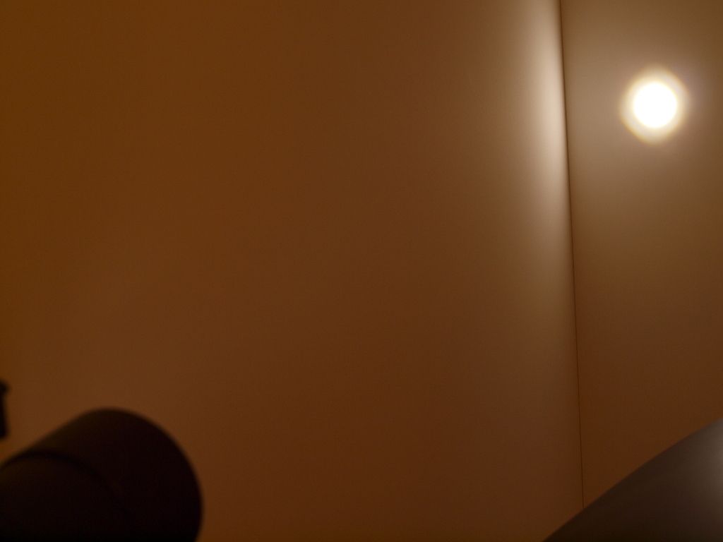
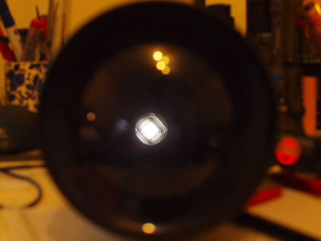
The image of the hotspot is only at a meter so it’s way out of focus (the die image only forms properly beyond 15m) and the one from the front is overexposed so greatly exacerbating the amount of spill hitting around the die. Neither give a good idea of what the main collar image is actually doing.
This is what I did to align the collar:
With my dome I see a distinct and defined primary image that I can use to visually align the collar onto the emitter. It’s a clear and pretty clean disk of light that can be shifted on to the die relatively easily getting it centered and in the ballpark in terms of focus.
Tuning the up and down focus is next to impossible to do by eye so I then adjusted and shimmed the collar checking lux readings periodically to try and find the focus sweet spot. The collar in it’s stock form combined with the height of the noctingon can easily pass through the entire focus sweep without having to remove any material. That makes it pretty easy to find a spot close to the focal point, as long as you have suitable shims to make fine adjustements.
However even at the best focus spot in terms of spot brightness there is still a fainter amount of secondary or more diffused light around the main image that then illuminates a part of the substrate around the die. This is pretty dim and barely shows up around the beam hostpot. It’s most noticeable on the annoying silver parts of the substrate, if it were all green it wouldn’t show up at all in the beam.
I’m pretty confident in the main focus and alignment of the collar so this unfocused secondary light is probably just a result of some geometric or surface flaws in the melon/meat baller, as you said earlier there’s always going to be some issues in this regard and some light will not be reflected back exactly to where it came from.
I suspect you have a better dome to work with if you’re not seeing any of this spill but certainly the image above greatly exaggerates the effect.
I guess melon balls are not known to require perfectly spherical dimensions so I may be asking a bit much from a kitchen utensil
Still, more than a 25% boost in lux and a complete elimination of rings or artifacts in the spill beam has already made the effort worthwhile.
I adjusted the photo to see a little more definition of what’s going on.
While it’s true the die image is not perfectly in focus a shorter ranges, this one appears to be in well enough focus at this distance to see what’s going on at the die plane. I see a perfect circular die, so it is in enough focus to know that the projected object shapes are defined near correctly. The light around it appears to be a lot of extra light that is window-reflecting or reflecting off the die base metal upon return. You may actually get quite higher gains without the protective window reflecting. On Luminus chips, the window can be removed carefully by slicing and pulling it up making sure never to push it down on the bond wires. Once you get it to lift, it should be pretty straightforward for you to do easily, though. Just make your glue slices very carefully first, if you do it.
What may be happening also I highly suspect is the short cylindrical portion of your RA near the base is reflecting some spill light cross directionally and bouncing around inside. Masking, and coating that with high-temp black flat paint may help quite a bit to rid some of that non-useful light.
The best focusing apertures I have used are meniscus hemisphere (dome) lenses. Very large lenses though, 60-70mm diameter, would be for very big lights—was going to do an Edmund 200mmx400FL condenser lens (+ collimating lens near LED) since those big Edmund PCX lenses are only $135 for a 200mm and use one of them. I am going to 3D print some lens holders in the upcoming months to hold large lenses like these is certain tube types that are available to make a cheap giant deck tripod light, once I find some good looking tubes with (hopefully) threading internally for cheap, if I search long enough. I may just wrap some fiberglass tubes and then sand and paint, which is fairly cheap to do (woven glass or carbon sleeve can be used to get great tubes by using heat shrink tubing on the outside to heat and squeeze out excess epoxy when laminating the fabric, then slice and peel shrink tube off when cured, you get a gloss finish). If I could find a 200mm ID camera tube like yours, would be amazing to pair up to one. When I say “only $135” for those lenses, note that if you use the total diameter area as a baseline (not actual lens-aperture which will be a few % less), a 200mm lens nets over 31,000mm². Compare that to a 75mm lens, at 4,400mm². That’s 7 times the light collection of a 75mm. Imagine buying 7 quality 75mm lenses; it would be much more than $135, in other words. Sounds like a deal to me.
Anyways, your RA is high F# I would say. So you’re capturing a lot of light for reflection near the main central intense beam that’s for sure. That’s not good nor bad, just says you’re recycling a lot more than average, so gains should be easily higher than an RA with typical 2:1 ratio (height / aperture hole). When you open the hole like you were saying, good tip is to aim to cover out to about 4mm ring around the inside lens edge and not more. Your collection (entrance) aperture size on the lens itself will be something smaller than its entire diameter since the light rays still increase in diameter more after they pass the first lens face until the second lens face defracts them for a second final bend into collimation. So if you lite the whole lens rear, a ring of rays near the edge will end up striking the lens rim inside the lens, not exiting in collimation—mine as well use the light for inside the RA instead.
I’ll whip the lens off once I’m happy with the light and won’t be doing any more experimenting, till then I like the security of that little protective window
Did you happen to take some output readings before and after doing this? Wonder how much is lost simply because of the window, quite apart from any light recycling issues or artifacting.
Yes, I was wondering about using something like that. Potentially trying one of those chemical glass mirroring solutions to create the reflective surface on the inside. You know the stuff they sell for making mirrored glass bottles. I think it’s a thin silver layer that’s deposited, but don’t know how suitable or efficient it would be here.
In any case I couldn’t find dome lenses small enough so I didn’t pursue it. Plus for a diy thing, grinding glass is pretty fiddly.
That sounds epic, hope you post up a build thread!
The only SBT-70 I have, I didn’t do this to. I’ve done it with SST-90s (Luminus uses pretty similar methods of mounting their lenses down, but of course SST90 has a dome not window).
The only reason I recommend it for maximum gain, is because anything reflective over the die presents the issue of added loss. There should be gains in an RA setup when removed, in that case. It may not be a lot of gain, but some intensity increase should occur. They mount the window very close to the die, so that reflections do not scatter around away from the die as you might imagine if it were 3mm away, for example. Since light faces an increased reflection value at higher incident angles to a surface, I only imagine it helping with an RA to remove it. Light should leave at higher angles, and also return at higher angles, with window removed.
I ordered a MakerGear M2 3D-printer. I cannot wait to begin printing some things for light projects. It can print down to 20 micron layer height. Once I receive it and get it printing well, there should be some interesting ideas it can bring to life.
Mem is the greatest aspherical flashlight expert on planet. You are probably "the one" I am waiting to change aspherical flashlight technology... And I am waiting since 2007.
As I told before; Aspherics are my number one choice since my first days of flashaholism. I would like to see some inventions on this field and not just "slap it with bigger lenses for better performance", and downsize trend.
I imagine one day small pocket zoomie will have at least 500kcd throw performance. Zoomies are lights with biggest potential and they have incredible performance in certain light applications(like IR for example), and I can bet that some person like MEM will make extraordinary versions of them.
It’s possible right now to have 500Kcd in a small diameter pocket light. It’s just not possible to build them cheaply, unless CREE decides to employ me. But, total lumens are not high, energy density is.
Thanks for the graph MEM but those are very old news … and furthermore only help make it looks more complicated than what it is in reality.
Almost everywhere that I read in your post it seems that you are obsessed by “reflective index“term. Maybe its u are working to much with collars and in your mind everything than, go and explained by reflective processes. I have to inform you that in physics there is another cool effect that is called refraction …. And yes looking at it and using the logic little bit to much one can look at it upside down and “explain” refractive phenomenon without the need of refractive explanation. This can be done but it complicate to much without the need of it. Those two processes are like two opposite sides of the same coin.
Why I am noting this?
Making it more complicated than make it almost impossible to explain further phenomenon’s. U than limit yourself only in saying facts without the ability to explain them. Only telling them it’s not explanation.
Why dedomin a led makes it more yellow but adding collar make it more yellow too?
If it is the same reflective process than when we should see the same thing when we put the dome and also put the collar. But in reality the dome make it whiter but the collar make it more yellow…
Its simple, collar phenomenon can be explained rightfully by reflective processes (because that is what it is happening in reality) dedomin its not the same. Trying to explain by reflective processes put u in the wrong explanation. Its not that blue light like to be reflected more … but it is this: blue light escape more from phosphor layer, without being trapped and converted in yellow end red even more. In fact it is converted but in less % than without dome. The mix in the end result tend to go over blue spectrum, more blue +less red and yellow = more white!
Without dome and her refractive properties (lower than phosphor layer but higher that air) less blue light escape from phosphor (and this is = with les total output) and also more red and yellow (but not all is converted some is lost in thermal transformation!) so the tint go yellow and total output is lower.
Explaining little bit further…
What happen when we live on a slight layer of dome after dedomin (hot dedmoe )
The thin silicone layer even that is very thin still does its job as a refractive medium and helps that more light escape from phosphor. Hence it again the same story more output and whiter tint. Still from a theory point of view there should be little bit les output and slight tint shift because of the shape of the dome. Being spherical the dome help more
I have explained well past this phenomenon into what is occurring in reflective apertures. I even refer to the experiment I did with a slice of dome gel over XM-L as to show little tint shift as predicted because it’s exactly as you say, refractive indexes as well. Which will have a very similar effect with XP-L Hi-Intensity LED. It is when there is an air cavity and a reflecting surface medium that we also use a reflective % of surface at various wavelengths.
I just noted a problem in another thread when people use polished stainless steel because 450-455nm reflectivity is <30%. So, little re-excitation of yellow YAG phosphor will occur when little percentage of 450nm light makes its way back to the die phosphor substrate.
There has been a lot of writing all over the place on BLF on this subject, but I well understand the excitation process at hand within an LED.
InGaN semi-conductor releases 455nm~ photons after electron field excitation and rapid particle decay of electron energy state. Photons can be absorbed by the YAG/celium phosphor to convert into lower energy wavelengths, but some stray photons will bounce around and strike the semi-conductor region again, creating electron saturation, and increased heat buildup upon the InGaN semi-conductor region.