unfortunately i have no bench power supply ![]()
Cree is it so far on the current vs. lumen output chart and they stop at 1.05 amps. Some how I think this one doesn’t need that much extra oomph. If charts are to be believed it’s up to 1833 lumens at only 13.5 watts for the high density. Flat dome (high intensity) being 1483 lumens at the same wattage.
I was going to build this light today, have all the parts sitting out, waiting to find out how to figure the sense resistor requirement to make the LD-2 output the correct amperage. Can’t find it, not getting responses to my questions in the wind…
i can look tomorrow what led4power soldered on mine…
I found most of it, for 4S cells the 750kOhm resistor on the right of the pair needs to be 250kOhm, or 3 of the 750’s stacked.
There’s a formula for figuring the sense resistor, gotta get to work on that…
Picture of the 4S and 3S config changes HERE
prepared for 4S (tiiiny thingies!)
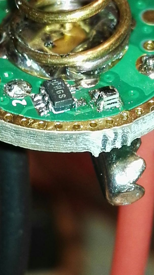
the sense resistors

hope that helps
If anyone wants to dump some or a couple of a quantity order they buy, let me know and I will buy the extra XHP35’s. ![]()
I can plot Vf-amps all the way til they pop if needed, though I imagine someone is probably getting the job done while I say it.
Is this it Dale?
Yes, that’s the pic I found explaining series cells, but here’s a better explanation directly from LED4POWER
“1.Change 0402 750kOhm->0402 250kOhm on spring side,solder jumper is number 2!
2.Change shunt from 1mOhm->2mOhm
3.Change max. Current set resistor 0603 150kOhm->0603 180kOhm(or 225kOhm if you want 2A).”
This sets up the LD2 to make the correct power level through a change in the shunt as well as the sense resistor on the inside of the board, and a change in how the driver see’s the series stack on the outside of the board.
I have the required components on the way from Mouser. ![]() (hate it when I have to stop a build and wait for parts! I forget what I was doing!)
(hate it when I have to stop a build and wait for parts! I forget what I was doing!)
I've been seriously working on a small booster for about 4-5 days now. It is easy to copy a reference design and hook up a half-cocked constant-voltage single mode booster, but to make a full-fledged LED driver (constant current, modes, low voltage protection) it is much more involved.
Here are the issues with most high-powered boost converters that will actually fit on a small board:
- You need to convert from constant voltage to constant current
- While you can make CV kinda work, it isn't right for an LED load
- Add current sense resistor which provides feedback instead of voltage divider
- You need modes
- Bias the feedback pin for modes if you want constant current
- You can switch into different resistors for limited set modes (ala DQG Tiny 26650 boost driver) or;
- You can use an opamp and RC/LC filter to convert the digital PWM to an analog voltage to bias the feedback pin
- Otherwise you can use a parallel shunt FET (quick and dirty, but not optimal)
- You need low voltage protection
- You can use a uC or discrete voltage cutoff solution to pull enable pin low
Now, take all of that stuff and stick it onto 17mm board with a suitable inductor and keep it from overheating. 
If you guys are interested I do have one option for the driver here. Not an ideal solution ( like a killer boost driver would be), but its a start :)
https://budgetlightforum.com/t/-/34954
grmpf…
big throwback ![]()
the driver poped when it went to high ![]()
the voltage regulator vaporized…
i converted a king clone to 4S using the original driver as contact plate and measured 16,4V at my plus and minus
hooked up the driver ( which worked when i tested it with a 12v primary (cell from a remote)
Could you send me PM with some pictures,to see what exactly happened?
MCP6H01 is rated as 16V opamp,17V absolute max. rating,so it shouldn't burn in theory.
(actually I picked this chip having 2s in mind,3s and 4s combinations are very rare for 17mm driver format;it's very hard to find high voltage IC in very small packages,there are very few higher voltage opamps in sc70 package,but they have high quiescent current).
Maybe 4 series in LiFePO4 cells would work better with a lower voltage?
dchomak wrote:
How hard could it be to modify a SRK FET driver to run on 12v? If on board regulation of the components other than the FET could be done, it would be rather simple, right?
Something similar, maybe a little more sophisticated, to the Zener mod.
This regulator should be a good way to run the MCU on a DD driver. It requires a cap on input and on output. The data sheet says proper ESR is critical on the output cap. It says a resistor value of 500-mΩ to 1-Ω must be used in series with output cap for ceramic caps to simulate ESR. I have a few on the way to use in 4S buck drivers. I'll report how they work out, but I don't expect any problems.
I don't have exact figures because my sphere is not calibrated to measure this way, but here is some data I compiled today.
The main reason for the test was I really wanted to see where the dead fall for this emitter was. I found that I could drive it to 3.5A with no problem, but I still suspected this was too high.
My guess was that this is 4 XPE dies and from past tests I know that 2.2 is about the max per die for those. On the SC5 platform we did gain a hair over that but not what I was expecting. At 2.5A this one is completely tapped out.
This was done with a C4 bin high intensity.
| Cree XHP-35 | FC | volts | estimated lumens | |
| 1A | 244 | 12.8 | 813 | |
| 1.5A | 327 | 13.4 | 1090 | |
| 2A | 381 | 13.9 | 1270 | |
| 2.5A | 411 | 14.5 | 1370 | |
| 3A | 408 | 15.1 | 1360 | |
| 3.5A | 336 | 16.2 | 1220 |
|
Again the lumen numbers may not be are not perfect, but the percentage of gain at higher current is going to be very close. This was also done on a sink that is better than in any flashlight, so that will be a consideration too.
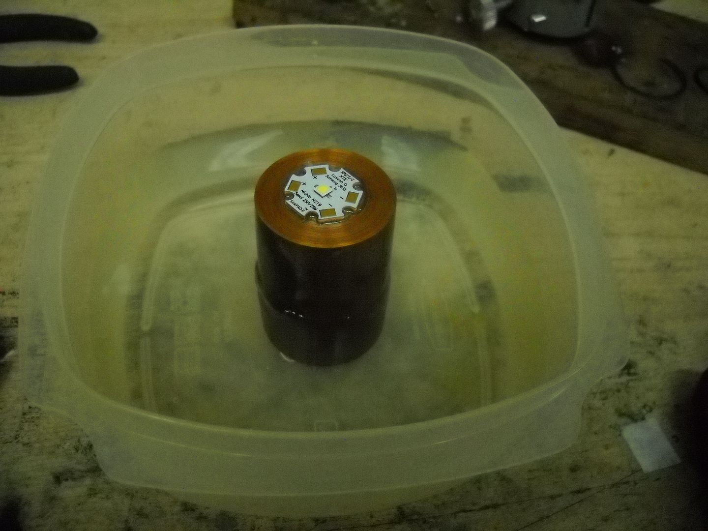
I reflowed it to a copper bar, and set that inside a pan of water. Very effective.
Honestly I really cant say that I am impressed with this emitter. Granted if I had a top bin high density vs a 1 bind down high intensity the lumen output would have been a few hundred more.
I guess I should have read the data sheet more carefully before I got my hopes up with this.
Even if my numbers are a bit skewed ( they could be). I have de-domed U4 bin XML2s that are properly driven 4ish amps that out perform this emitter. Both higher lumens and equal or greater lux.
Better lux next time I guess :)
Great job VOB! Thanks for testing these. After playing around with cree’s characterization tool a few weeks ago and comparing with other emitters, I had a feeling these would turn out to be duds. But then, we would never know till someone quantified the results while overdriven for max lumens… something cree falls short of in providing data past its recommended maximums. Thanks again! :bigsmile:
There goes my plans for a 12 x 18650 BTU shocker mod with 3 XHP35’s. ![]()
thanks for the numbers VOB!
looks like i spent money on the wrong horse…. ![]()
.
so: what can be driven with a 4S srk clone? ![]()
VOB, thanks for tackling the extended current chart. I thought we had a good LED here your chart was a 1/3 less than the product chart how ever. One hope left the High Density top bin claim about 1 1/2 times greater out put than the LED bin you tested. Gains in current I think showed the trade off max at about 1.5 amps before gain really slows down. Still 20 watts is a lot to bleed out in a conventional light design. I still would like to see a single cell driver for these voltages as we still have the XHP-50 and 70.
Excellent data VOB. Not the news we were hoping for, but hopes don't create lumens without some good hardware to back them up.
Love the copper bar in water heat sink idea for testing. Very nice.