DB I’ve add your video to the op. Along with some explanation as to why it’s safer. I hope that helps a lot of people! Thanks!
Let’s say “potentially” safer, we want people to think on the side of safety while they’re modifying these lights, right? I mean, reckless abandon is well and good when with a consenting adult but sometimes thoughtful care and consideration are appropro…
Yes there will always be tree burning. And triples you can weld with. Right? ![]()
Wait til you build your first small triple, it’s so exhilarating, scary, and just outright fun you’ll wonder what took you so long.
The first time I saw 12A in a smallish light, man, what a trip! Then I saw 16Amps, 17Amps, holy cow, I was afraid to turn it on! And now I have a quad Titanium X6 pulling 21.3A from a single cell, yeah, it’s just freakish and fun and mindblowing and dangerous and and and…
You’ll see! You’ve got the bug! ![]()
If you want a fuse, it’s pretty simple to do. Just don’t bypass the spring. The spring will act as a fuse.
I know this because I’ve destroyed springs that way. It actually works pretty well, and prevented anything else from getting damaged.
After a night's sleep I understand the safety concern of an outside spring bypass a bit better: I know I make solid solder joints but not everyone will make a good job of it, and you don't want to have it come loose. I think what TK says is a pretty good point: the driver spring of the BLF-A6 is not so long, so the gain of a bypass is a bit less so just leave it out. You can still do the tail spring bypass any way you want it because when it shorts there it is not a direct battery short but the light just switches on (in my case in moonlight :-) ), much less of an issue for something that will not often happen anyway.
Last night I did a spring bypass on both springs. Testing with a 25R freshly charged with 4.19v yielded 6.7a on my Fluke clamp meter…wow! Is anyone else seeing that many amps? Hopefully that poor little XPL can live at that power level.
The driver on this light is awesome;
Great UI
Nice moonlight
Lots of top-end output
Many thanks to everyone who worked on this project!
wow, that is more than anyone got yet, you must have had a very low voltage XP-L by chance. I have had XP-L leds that went to over 9A en ones that blew at 7A, so you may just be lucky with this one :-)
Good work Scot! You are now solidly addicted. ![]()
I have one that’s doing 6.2A on a Samsung 30Q, an HI variant actually, but most don’t go that high. Like Jos says, it’s the luck of the draw.
Hey Dale, since switching to your method of using my clamp meter to Measure amp draw, my readings have gone up, a lot. Here’s another point worth noting, I took the battery directly out of the BLF light after testing and placed it in the A6 I won in your giveaway, and amp draw dropped to around 5.4. Edit 6.1a
Likely to be an emitter binning difference, each step on the bins is approx a 20% gain in output. We did see some dramatic shifts in the equilibrium when Cree made the last changes and high amperage is not common anymore, while output can very well be the same.
At any rate, a 500-600 mA difference is fairly normal between 2 identically built lights. It’s always difficult to get em exactly the same.
I’ve also built a light, ran the tests, wrote down everything as it happened only to come back later and find new tests give different results. The cells lose capability with age and wear, the emitters break in differently, whatever causes it, it’s a fluctuating set of parameters that befuddles me on a regular basis.
I'm loosing faith in my 14 AWG DMM lead setup now, after hearing these crazy #'s... Wow! Is there any reliable way you have to measured tailcap amps on the same setup you used the clamp meter on?
I'm seeing the same as you Dale. Generally months later, #'s go down, not always though. My triple X6 that was ~4200 is now like 3900 or so, for example. Cells sure do lose it. I'm think'n I'm not smart bout storing them lower - I tend to keep my cells charged up, which is probably not helping.
I also wanted to state that while the differing tube lengths are a crappy ordeal esp. for any protected battery people (although springs on both ends helps) that the tube length in itself shouldn’t affect power through the light. The problem it seems is the length of the threads and/or how deep the caps are threaded. You’re running out of thread before the un-anodized portion of the tube is seated properly. Also be sure that your retaining rings are tight as they need connection to their respective boards! As I and DB have mentioned be sure your tube is not reversed (clip slot near tail). I am already guessing you are thorough enough to have checked that. ![]() Please be aware that some of my posts are for anyone reading in the future as well.
Please be aware that some of my posts are for anyone reading in the future as well.
Hi Tom, just measured the A6 that hit 6.7a on my fluke clamp meter. It reads 5.4a on my Klein DMM with 14” 12g a leads.
Occasionally I will interrupt the negative lead on the star and put a loop between the lead and the pad to clamp onto, thus getting an actual emitter amperage reading. I keep the loop as short as I can fit the clamp meter on comfortably, usually about a 3” lead.
12 ga solid wire from Romex in about 3” lengths and folded over on one end to fit in the DMM give very close to the same readings as my clamp meter. You just have to be careful not to be measuring something with more than 10A draw. My clamp meter reads up to 40A.
Hi Scott - hhmm, that's interesting. What exactly is the technique you are using with the clamp meter? It could be a true 6.7A, but maybe you won't see that high # when all is assembled and buttoned up? Usually a light box/sphere is the ultimate test, if you can test output while doing the amp measuring method, then test it fully assembled. I've seen my tail amp measurements reading low sometimes: output is lower when jumpered with the meter, compared to fully assembled (bypass's of course).
I'm thinking you are doing it with a heavy gauge wire at the tail end of the battery/light?
Clamp meter and short thick wire is the only accurate method to measure currents in that range and with voltages arround 4V. Regular multimeters have too high internal resistance and introduce large error.
I measure arround 5A with my Fluke187 and above 6A with the clamp.
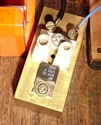
I use another way that works well. I have a 0.01 Ohm resistor (1% accuracy, rated for 20A) mounted on a piece of brass with the leads soldered into a terminal block. Not on the picture but I use two 10cm pieces of massive copper wire soldered to solid copper clamps for connectors. I measure the voltage over the resistor, current is 10mV/A.
That is indeed more accurate than a multimeter but still there are 10mOhm plus two wires added into the current path (let us assume 20mOhm total including the connecting wires, connectors and soldering).
20 mOhm multiplied by 6A produces a 120mV voltage drop.
This may not seem much but with the exponential VA curve of the LED 120mOhm will give you a difference in the measured current of at least 0.5A. See the attached Cree XML diagram for example.
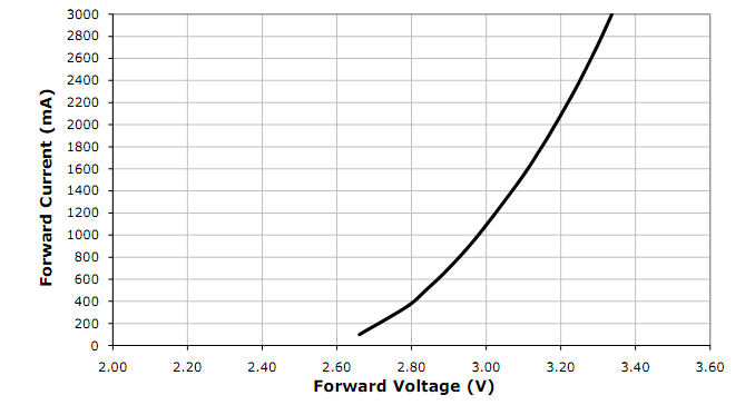
For comparison I use a wire for my clamp that is less than 2mOhm.
I'm not sure the connection set-up for the sense resistor gives another 10mOhm (I hope less), I did not check that but I can do that and report here, I'm curious too (not before tomorrow btw). The 0.5A drop at 120mA is also correct for the XP-L at 6A btw.