one thing i dont get is people modifying digital multi meter (dmm) leads i have a cheap dmm and a fluke dmm they read very very close to each other i belive the fluke leads are calibrated with the unit (and should not be changed).
i also belive the cheap dmm is to, i have used shorter larger dia leads with less resistance it gives higher current draw test on the cheap meter but when compared to my fluke dmm and a family friends new fluke the readings are much higher more impressive but to me they are fase as its messed with the calibration of the meter and the meter is giving fase high readings i trust the flukes readings over a cheaper meter with the leads change.
i did this test as i have seen people of here recomending people to modifying there dmm leads when they have a torch or a battery with low results or when they buy a new cheap dmm, but if they have not got a good ddm to compare the results to how do they know the dmm is under reading or maybe not even over reading before the modifying the leads and how do they know its not fase reading after the modifications, how do they know the dmm leads are not calibrated for the dmm and are with the dmm tolernces before it left the factory as one would think they are with in a small percentage.
so how many reveiws and how many current draw tests have been posted with modifed dmm,s that could well be inacurate are people chasing the fase high.
Most DMMs measure current by passing it through a small value (low milliOhm) resistor, known as a shunt. They measure the voltage drop accross the resistor to determine the current flow (Ohms Law).
For current measurement, the leads are irrelevant to the measurement. The only difference thicker wires will make is that they may ALLOW more current to flow and be measured.
Most meters that I've played with (From 10 dollar specials to the 50,000 count Hioki that I have at work) are actually pretty good/accurate at measuring current since it's such a simple measurement. They're really just measuring voltage(drop) and converting it to current.
larger shorter leads will give less resistance and have less voltage drop but if you have 3 multi meters one 10 buck special and 2 flukes reading all the same but you mod the leads of the 10 buck special and now its reading higher then then the two flukes would you say the fluke,s are not reading correctly and the 10 buck special with modded leads is reading true.
e.g so you measure 3 amp,s to the driver with moded leads 2.5 amps with the two flukes but the wires from the driver to the emiiter is less then 1mm thick so its all irreverent lols i feel the leads should not be modified its just add's more variation as it comes down to what wire is used and then lenght, there is enough variation between users, batteries, chargers and the torchs.
It does matter. When you connect a meter, you're adding resistance (voltage drop) to the circuit. The battery tube is so close to zero-ohms that it's barely worth mentioning. The thickest wire you can use for leads will change the circuit the least from it's normal operating model (battery connected directly to tube), so that's the reading that most closely mimics the circuit in normal operation.
Taken another way, No matter how thick the leads are, they are always going to be worse for the circuit than the circuit usually is. This means, even under the best circumstances and with the thickest leads, you're still going to read a little LOW compared to what the real current is with no meter in circuit.
The highest reading you can get, using the thickest leads you can find, will be the best measurement of the real operation of the light.
I should add, this discussion really only pertains to direct drive or linear regulated applications. If there is a buck, boost, or buck-boost regulator between the battery and the emitter or emitters, all bets are off. In fact, smaller leads can end up showing higher currents.
This happens because the leads and the meter drop voltage from the battery, before the regulator. The regulator will do everything it can to generate the desired current at the emitter. In doing so, since it's lacking in voltage, it will make up for the lost power with amps. Power(watts) = Volts * Amps
so you belive there is not link between the shunt or resister for measuring amps to the standard leads of the DDM with calibration of the unit its self.
i always thought there was, meaning the shunt chosen was to suit the lead lenght, diameter and has to do with the calibration of the unit.
if we all modifyed our DMM leads to get the highest readings it would once again depend of what type of wire the diameter of the wire and the lengh used thats a big variable, where most cheap to top self DMM,s have a small % of + or - error
The actual current measuring of the DMM is completely independent of the leads used.
BUT the actual current is not, especially when working at low voltages. Both DMM and leads has some resistance and that resistance will drop some voltage. This voltage drop is usual in the range 0.1 to 0.5 volt, but can be as high as a few volts on some DMM's.
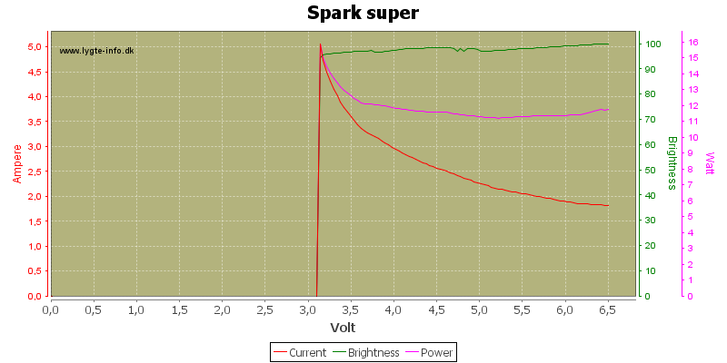
For most flashlights the current draw will depend on the voltage, but how it changes with voltage depends on the driver. Some drivers will increase current at lower voltage, other will decrease current.
Here is an current draw curve for a lights:
If I uses a LiIon battery with 4 volt and no DMM it will draw 3 ampere, but if I uses a meter with thin probe leads and looses 0.5 volt in the DMM+leads it will draw 3.6 ampere (Because the actual voltage is down to 3.5 volt).
Using batteries as source does also have its problems, there are not many LiIon batteries that can sustain 4 volt at 3 ampere draw, somewhere between 3.8 and 3.9 volt is much more realistic.
You get the right current when the resistance of the tailcap (switch) and the DMM is the same, and the DMM is accurate of course. If you use short and thick leads, sometimes you will measure much more current than the real ( when the tailcap is in the place), because the resistance of the tailcap is higher than the DMM+leads.
Vice versa if the resistance of the DMM is higher than the tailcap you will measure lower values.
There cannot be, as the leads are interchangeable and the DMMs are designed with this interchangeability in mind. In fact, you can buy different leads with different connectors and attachments/probes to suit different applications and professionals normally keep quite a selection of them.
Thus, the thickest and shortest leads will obstruct the current the least, with any DMM. To what degree such a reading represents the true current value we are seeking (the current flowing in normal use) will depend on how much the tailcap resistance differs from the compound resistance (DMM shunt + leads) introduced by the metering setup, as said above. I didn't do a reasearch, but I believe that unless you have a crap or worn-out (long overloaded) clickie and oxidized threads, the tailcap resistance should be lower than the shunt resistance in most affordable DMMs, so you can expect a higher in-use current than the value displayed by the DMM (battery obliging, that is).
I totally agree with everything except the last sentence. I think you are underestimating the resistance of the tailcap/switch. Maybe I’m wrong.
I still say that if you take a 4x7135 or 8x7135 driven light and use it with a test the current on a fully charged healthy 18650 you can see how close your measurements are to the 1.4A or 2.8A they should be drawing. The only thing I don't know is how much variation there is between those drivers.
With a regulating driver the voltage drop on the shunt and leads is much less of an issue since the driver will respond by regulating the current, as it does when the battery has lost some of its charge.
The current measuring problem pertains mainly to direct drives. (I didn't stress that point since Viffer750 had done that already.)
It would be interesting to measure the tailcap resistance on a few samples. I have thought of doing that but I have no idea of how to properly include the tailcap/tube thread contact in the measurement. Omitting the latter, it's still guessing. Besides, it varies a lot (relatively) with time and maintainance degree, I suppose.
Hmm, probing at the other end of the mounted tube?
I measured some of my tailcaps, and got 40-100mohm, some weaker were about 150mohm.
Resistance of my multimeters with stock leads: 60mohm, and the other 115mohm,
but dmm resistance decreased to 20-25mohm with thick and short leads. You can imagine the difference, when you measure with the modified dmm, and the light has a 100mohm tailcap...
Okay, some current measurments on my C8 xml:
dmm 25mohm -> 3.4A
60mohm -> 3.1A
115mohm ->2.6A
the "real" current is about 3.2A because the tailcap resistance is 45mohm.
wf-501 mc-e (tailcap 55mohm):
dmm 25mohm -> 3.25A
60mohm -> 2.9A
115mohm ->2.5A
the "real" current is about 2.9A
modified mte ssc p7 "xm-l" (tailcap 95mohm):
dmm 25mohm -> 4.1A
60mohm -> 3.6A
115mohm ->3.1A
the "real" current is about 3.2A
Actually since the can of worms has been opened, yes i agree. Sometimes the dirty lube in the threads can cause a limit on how much current can be passed. I experienced that with my DRY and some of my lights.
I'll try to measure with and without tailcap of some of my lights. For the additional wire needed, i will use 2 x 14awg so that the additional resistance is negligible.
But still, the most useful data i get is from the lux meter.
The DRY tailcap switches never malfunctioned even though passing 4A or even slightly above that regularly. I have switched off and on quite a few times already. Anyway I have a number of them as spares, they are rated 1.5A. Tough little chinese budget things.