Great info and pics. Thank you for all the hard work this all must have taken.
I initial impression was that you lost a little throw going to the 219C, but I think all the added flood and cooler tint threw me off. If you look at the dark area beyond the visible beam (first picture in Post 46), more items are visible in the 219C shot. Has something changed out in that area to make those objects better reflect light?
No, I don't believe anything has changed. I gave that first mouseover a good closeup look and they appear identical to me as far as what is visible in the distance.
-Garry
^
OK, I pulled up your pictures on a better monitor and I see what you mean. The throw is a little less with the 219C. What was throwing me off was the big dark trailer that was in front of the big structure or fence on the right and the house/building that is more visible on the right. I think that building is showing up more because it is now in the bigger flood of the 219C. On the better screen, I can see some stuff in the dark that I could not see with the 219C. Although the throw is slightly less, the bigger flood seems better for biking so that you can see objects approaching the path better further out.

Hi guys, long time no see.
I got a question on how to feed the ‘Kaidomain’s Gemini Duo / Yinding Clone’ when it’s 4.2V only?
I was thinking about a 2 cells parallel setup, but got problems to find a nice off the shelf battery case, most discussed cases are always 2s2p and therefore deliver to much voltage.
Garry how did you power up this nice budget bike light?
The price at kaidomain is really tempting.
Excellent work. Thanks for sharing. Very impressive. The colour rendition is superb.
I would recommend strongly against the 4.2v version. You get too much voltage drop through the thin wires. (See the thread I did on that light asking for help doing the sense resistor mod. I think it's linked further up in this thread.) I don't even use this light anymore. Buy the NW Yinding at GearBest. Much better light with great thermal path. Or the Nitefighter BT21 is an even better light.
-Garry
Thank you Garry !
I will follow your advice and look closer at the Yinding version at gearbest.
Since the nightride season in german mountain bike forum just started, I will probably get back to you (and everyone else in this part of the forum) with more stupid questions.
Though I’m still not unsatisfied with my Solarforce at the handlebar, I would like to get a bit ‘more’ or ‘better’, you know the old flashaholic virus……. sigh.
So I boosted my BT40S driver up to a calculated 4.0A (2A per emitter) and I think I might have this driver boosted for too much light (is there such a thing?).
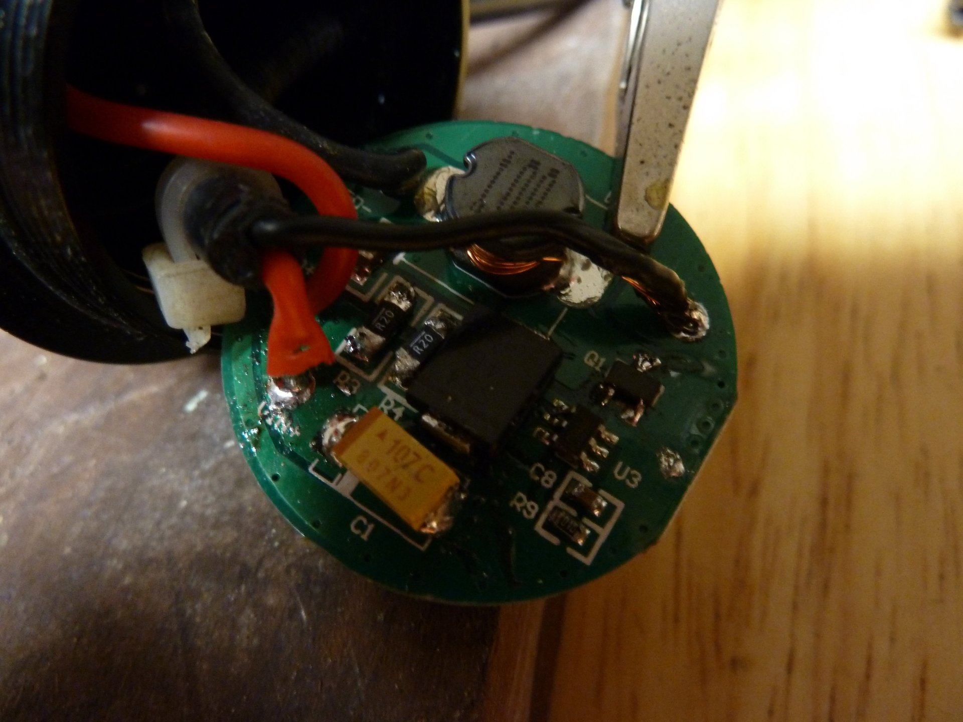
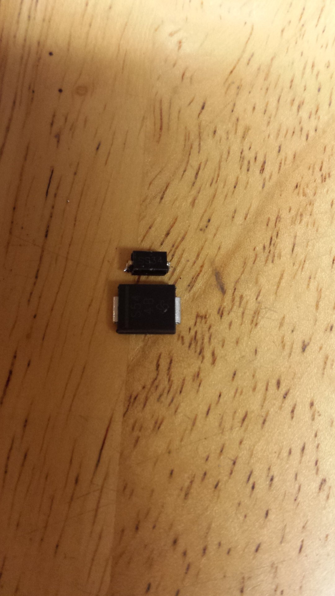
Some details: I've replaced the SS34 diode with an SS54 (which is huge in comparison - didn't realize that). I also replaced the stock "2300" FET (datasheet found here) with an "AO3400" ("A09T" chip marking - datasheet here). I happened to have the AO3400's on-hand from my Courui mod. Lastly I added (2) R200's on top of the (2) stock R200's. I had already replaced the power cable with the DX 20 gauge one.
Driver with FET and diode replaced but prior to adding R200's:
Comparison of the SS54 to the SS34:
Fired up my driver-modded BT40S for a bench test. Started out at 3.3A from 2 fully charged protected cells in my modded Fenix 2 cell case. Left her burn-in and no smoke, no hot components either. After 2 minutes the lighthead was starting to get uncomfortable to hold in my hand. Wow it's A LOT of light!
This light will definitely need powered from my homemade 2S3P pack made from those Xiaomi power banks. (Need to finish that yet.)
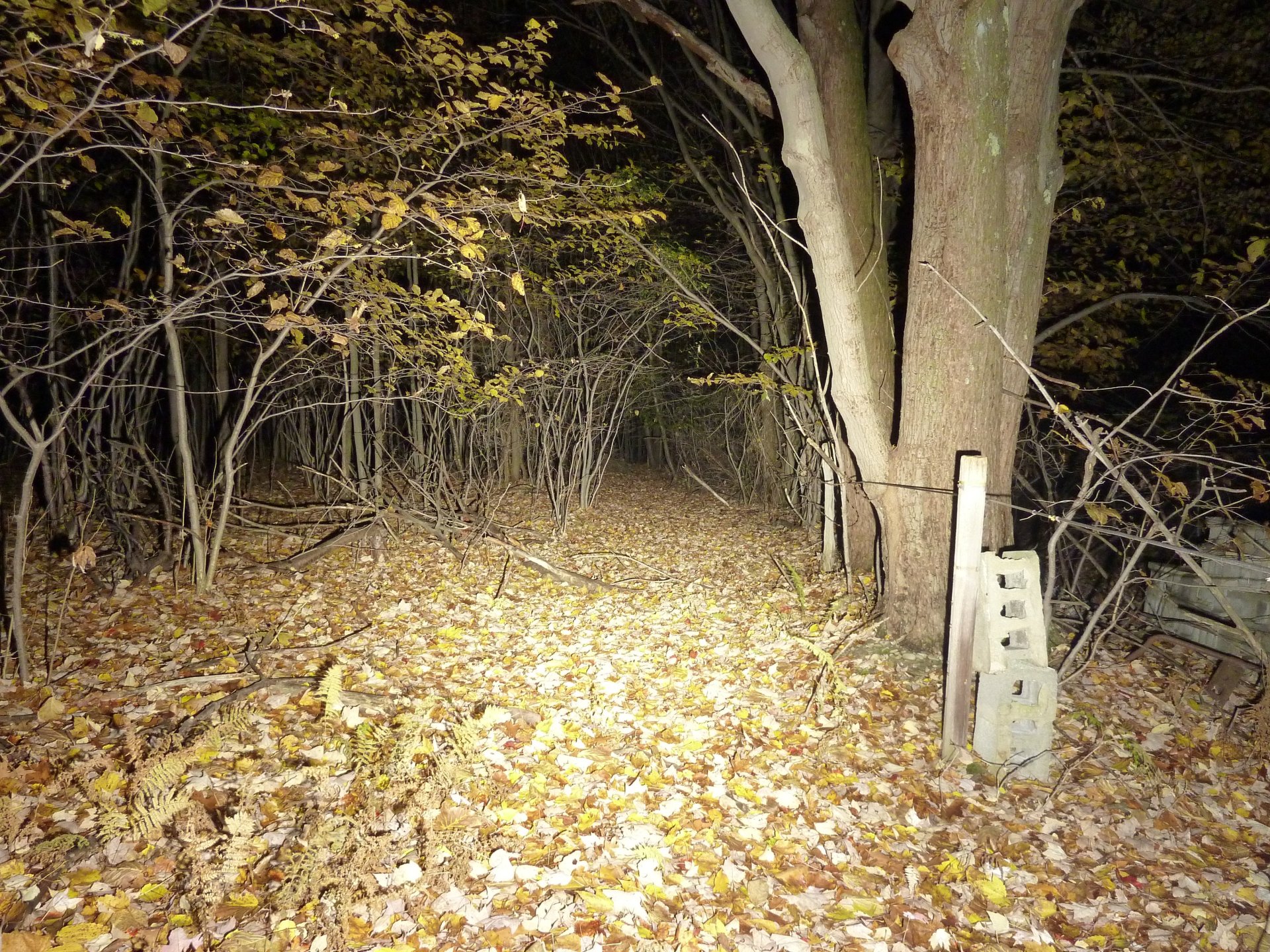
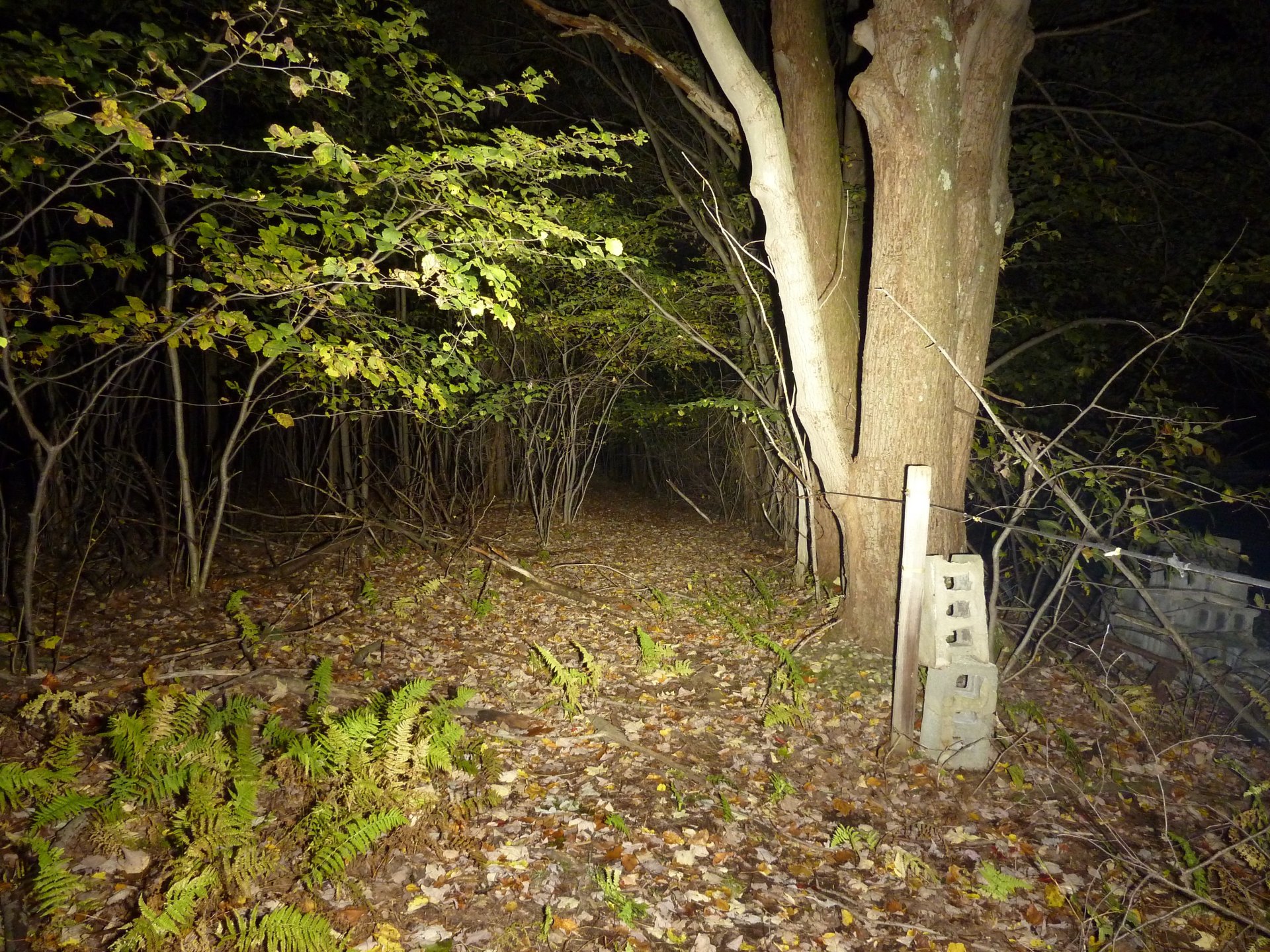
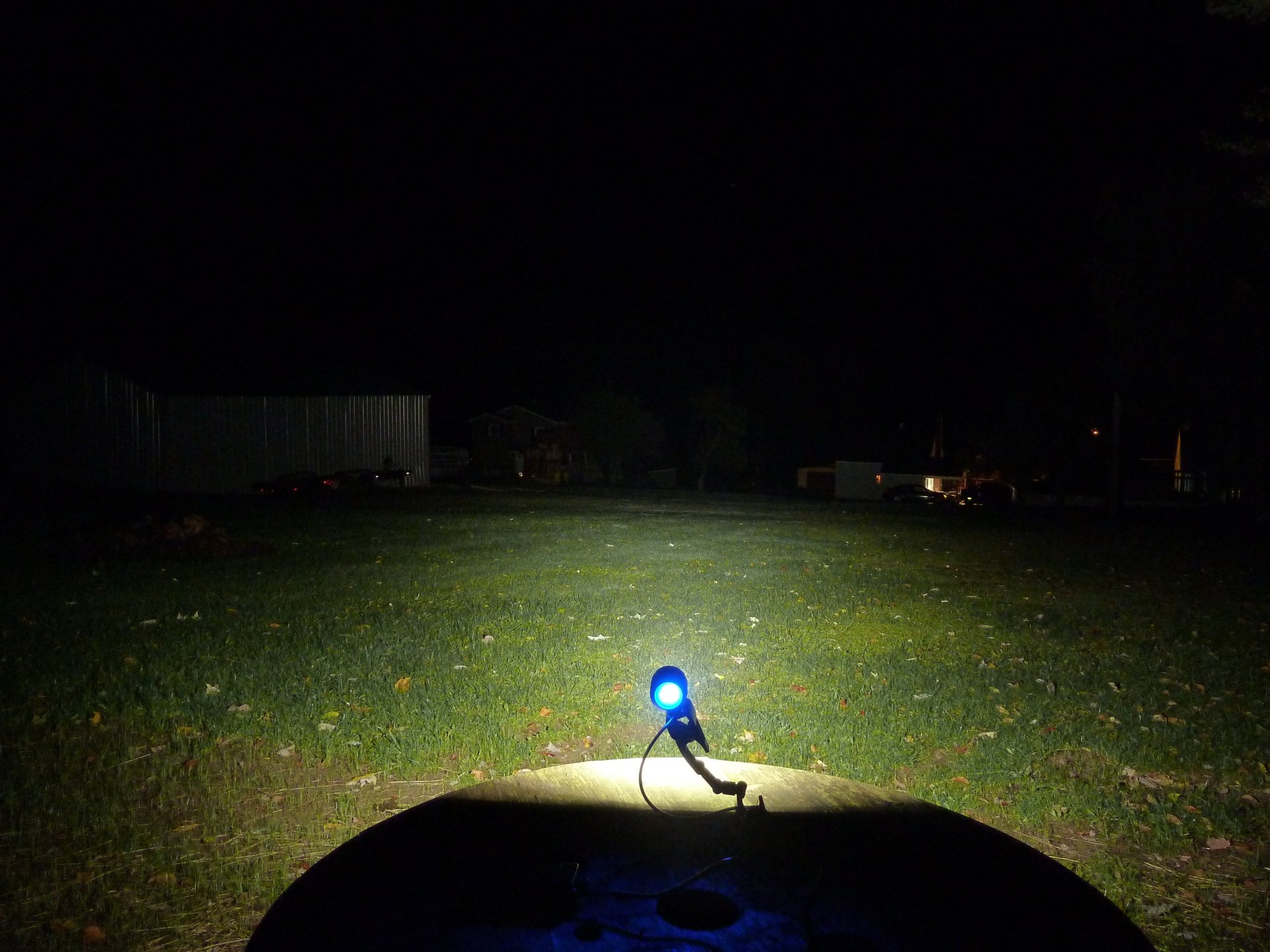
Here are some beamshots using 4 fully charged unprotected cells in my old Pannova case. Current measured off the case was 3.48A peak dropping to about 3.2A (so Turbo would give more output yet if I can get a pack to provide the full 4A output. (Remember, these beamshots are with Nichia 219C LEDs.)
Boosted Driver:
Stock driver:
Boosted Driver:
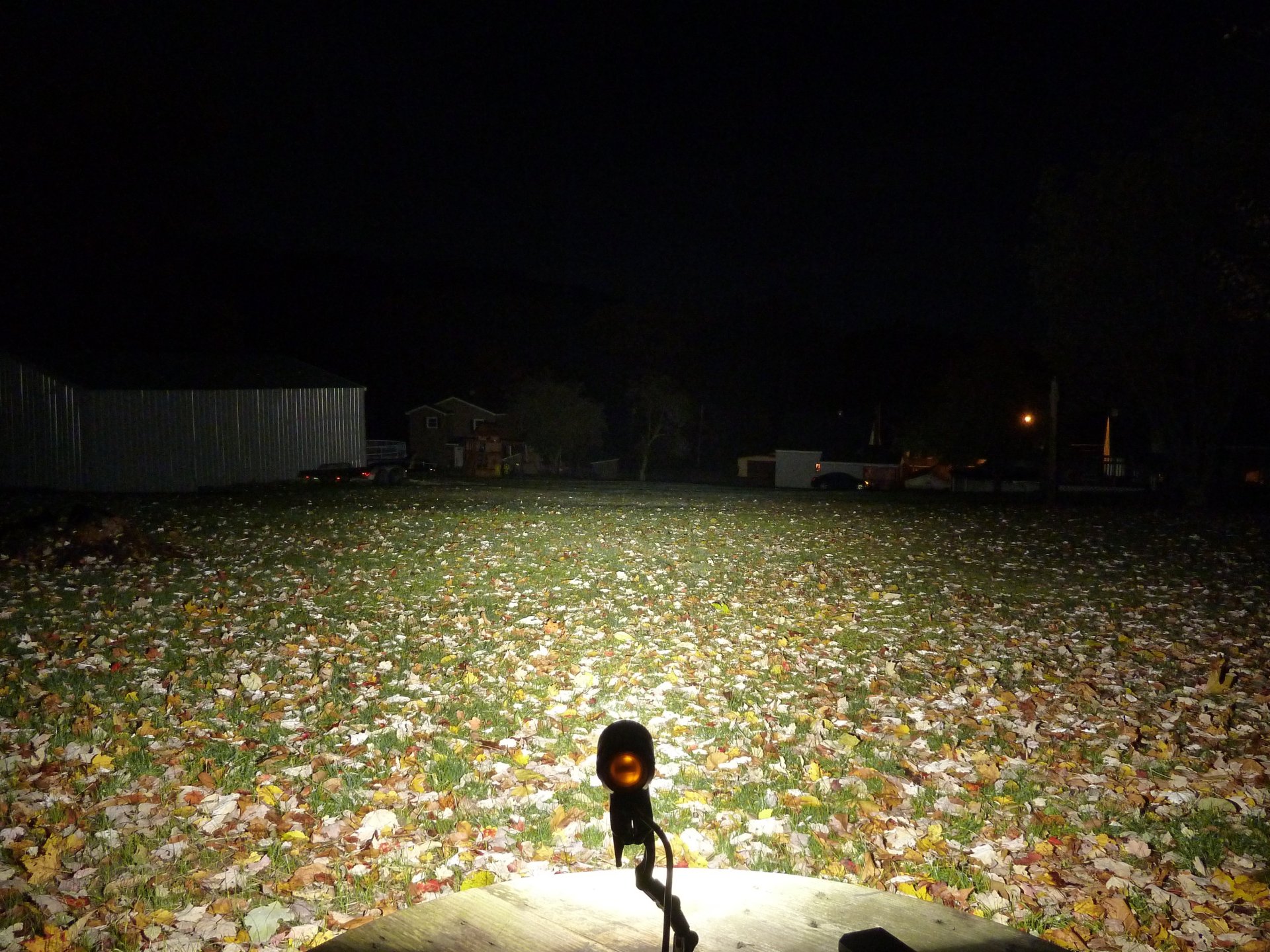
Stock Driver:
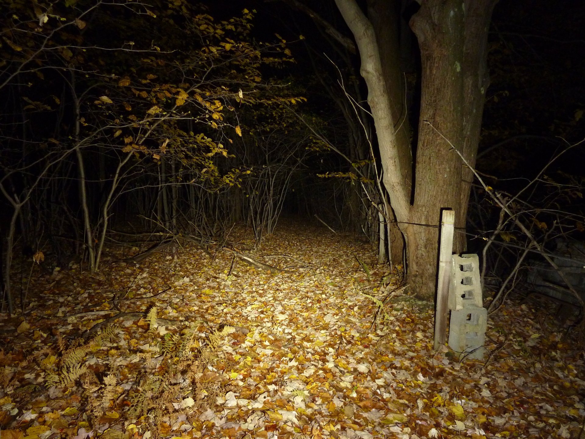
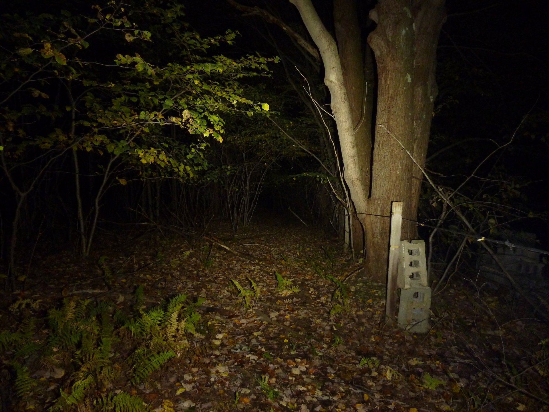
Wooded Mouseover: Mouse Out = Stock Driver, Mouse Over = Boosted Driver both "Turbo" mode :
Yard Mouseover: Mouse Out = Stock Driver, Mouse Over = Boosted Driver both "Turbo" mode :
And here's how much more output low has now (it pulls about 1.0A on low for +/- 500mA per LED).
Boosted driver's "Low":
Stock Driver's "Low":
Mouseover on the "Low" mode, Out = Stock, Over = "Boosted Driver"
So what do you think? Should I lower output to bring Low-Med-High back down some? And any thoughts on why "Turbo" doesn't pull full calculated current? Even the stock driver was calculated at 2.0A but only pulled about 1.75A.
-Garry
That is a seriously impressive improvement! ![]()
In this form it might work as a bike heater for winter use. The airflow coming past it will blow the heat back at you while you're riding :) . Perhaps I should work on a seat mounted light so I can have a "heated seat" :) .
-Garry
Guess you need to make a super tail light! lol
This is great stuff. Too bad I do not have those skills ![]()
I finally built up my custom 2S3P battery pack from NCR18650BE cells pulled from (2) Xiaomi 10,000mAh Power Banks (purchased for $12/ea), a 7A 2S protection circuit, a DX 20ga cable, and a hobby charger balance lead. It wasn't all that hard to build. The nice thing is that the cells come welded together in parallel out of the power bank. I used strips of copper cut from an old Dell PC heatsink to connect the bottom of the pack pairs. Had to solder the original "strip" material a few times as it rips so easily. I had to reset the PCM circuit with a charger before I could measure output voltage; that threw me off for a second.
Photos of the "copper strips" used to connect pairs (notice the ripped stock strip, which I later soldered back together). The trick of sticking the soldering iron between the copper and battery then removing iron and pushing together quickly (I used a popsicle stick) worked great, but you have to get things aligned right or else you probably won't get it back apart!:
All Wired Up:
All wrapped up:
And testing it out after a full charge (which takes a LOOONNGG time on a wall wart "1A" charger!) on my BT40S modded to a calculated 4A:
This is the highest current measurement yet on this light! Voltage is even high enough to keep the lights battery level indicator blue instead of red.
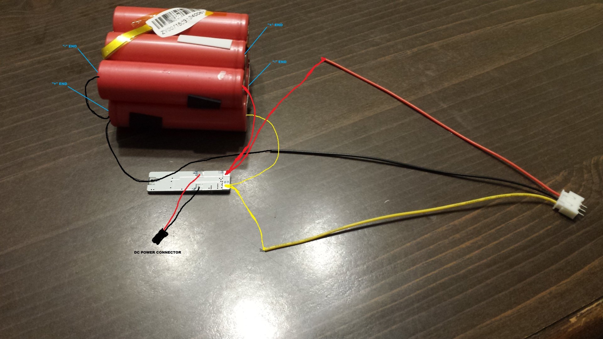
For anyone wanting to do this "build" here is a wiring diagram that may help:
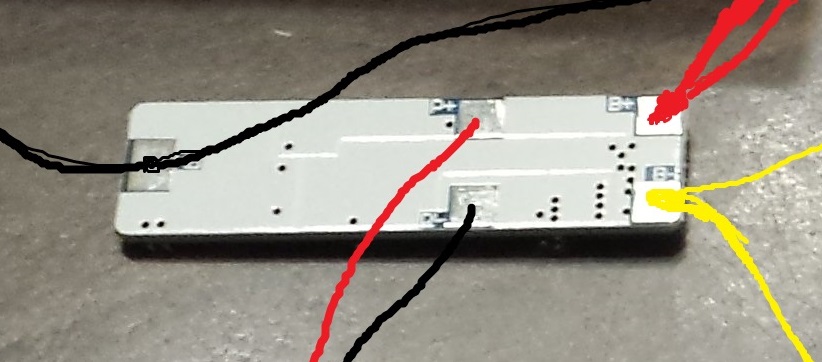
And a blow-up of the PCM board:
-Garry
does it make sense the use of a 2s1p protection circuit in a 2s3p circuit? if one or two of the 3 cells in one of the series is damaged, the circuit won’t be able to see it, right? I understand that discharging them is not a problem, because the circuit will trip when the weakest series reaches the minimum voltage, even though the other series will be much higher, but what about charging? it will only balance the voltage among the two series, but not the voltage of each individual cell into each 3 cell group
edit: just asking, I don’t understand it, not questioning your work
Balancing is achieved in two ways - 1) they are named brand matched cells and 2) they are already welded together in parallel which will keep them all equal. I don't think the parallel arrangement would allow you to monitor an individual cell.
-Garry
ok, so it only works ok based on the assumption that neither of the cells is gonna fail; aren’t there on the market circuits that monitor each of the cells? When I parallel cells, I prefer to charge them separately, and in the case of the bike lights just made 2 2s1p packs, and replace when needed. I also changed the power connector to xt60 in the light, so I can direct plug the pack to the hobby charger and to the light, and of course it’s harder to accidentally disconnect it when riding (mu battery packs go in the backpack and disconnected den in bumps accidentally with the old connector)
I believe the setup is the same in laptop battery packs; I don't believe those individual cells are (nor can be) monitored.
-Garry
Individual cells in a parallel set up can not be monitored.
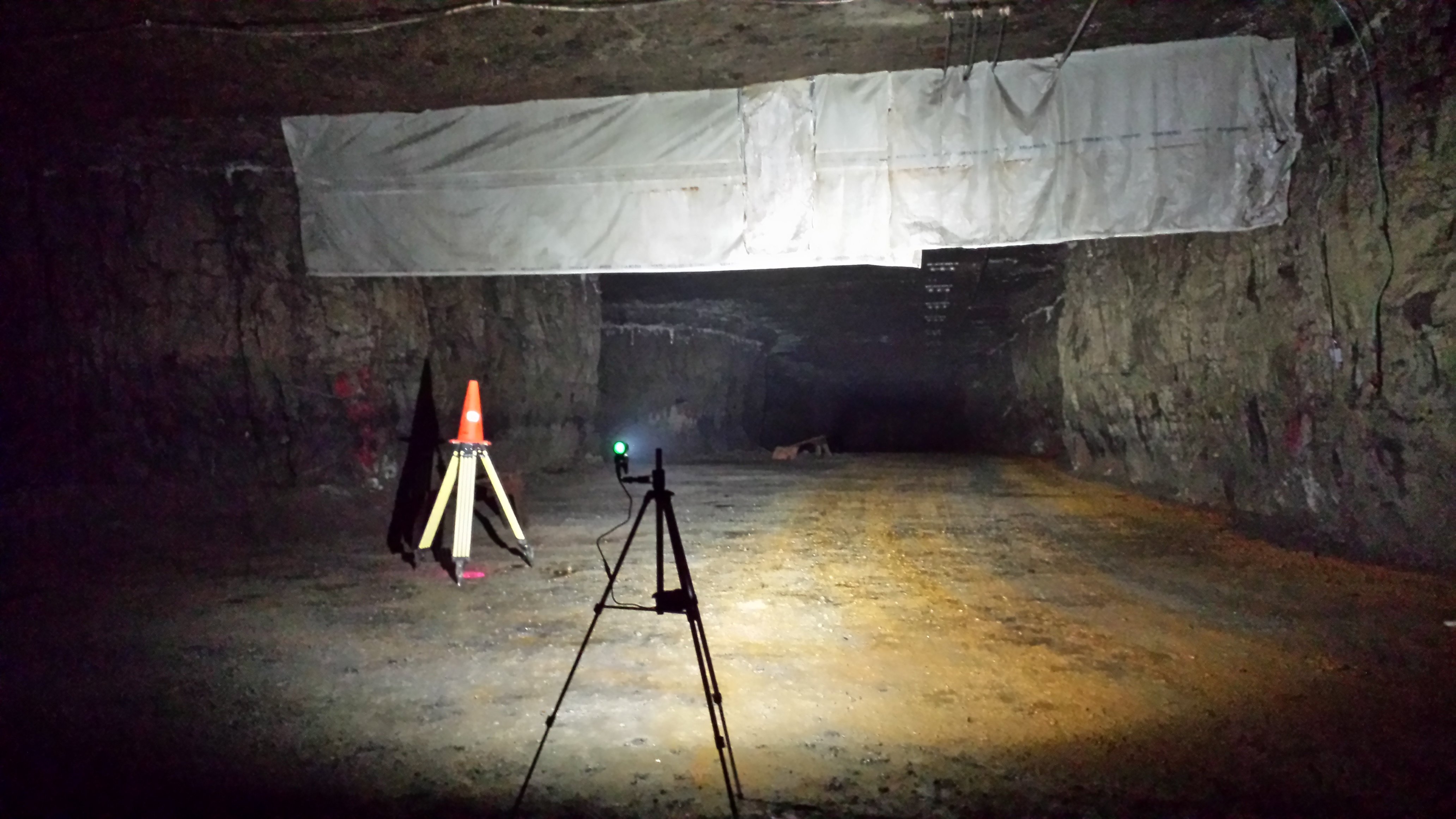
HOLY %$#@!!! Got a rare chance to go into an underground stone mine at work today and so I decided to take my modded BT40S and new battery pack to test it out. WOW! First of all, as I've said before, there is NOTHING like going into an underground mine (or cave) away from all other sources of light and being surrounded by complete darkness! You feel like you don't even know if your eyes are actually open or not. From my past two experiences in this same mine I learned that a 1,000 lumen flashlight is barely enough when you want to light up a large area. (By the same token, a 30 lumen light can be plenty to light up your general work area since your eyes are so adjusted.) Light just seems to be swallowed up by the dirt and stone (i.e. there's no reflection of light). I actually pulled our site "tour guide" (can't think what to call him - the young guy that took us to our destination wearing a +/- 150 lumen XR-E type miner's cap lamp) over and said, "Hey, you wanna see something that'll make you crap your pants?" Afterwards I then explained how I only have about $35 in that light to get that insane output.
(Ignore traffic cone which only served for my partner to be able to see that location during his setup.)
Here's a pic of my BT40S on "Turbo" (+/- 3.8A):
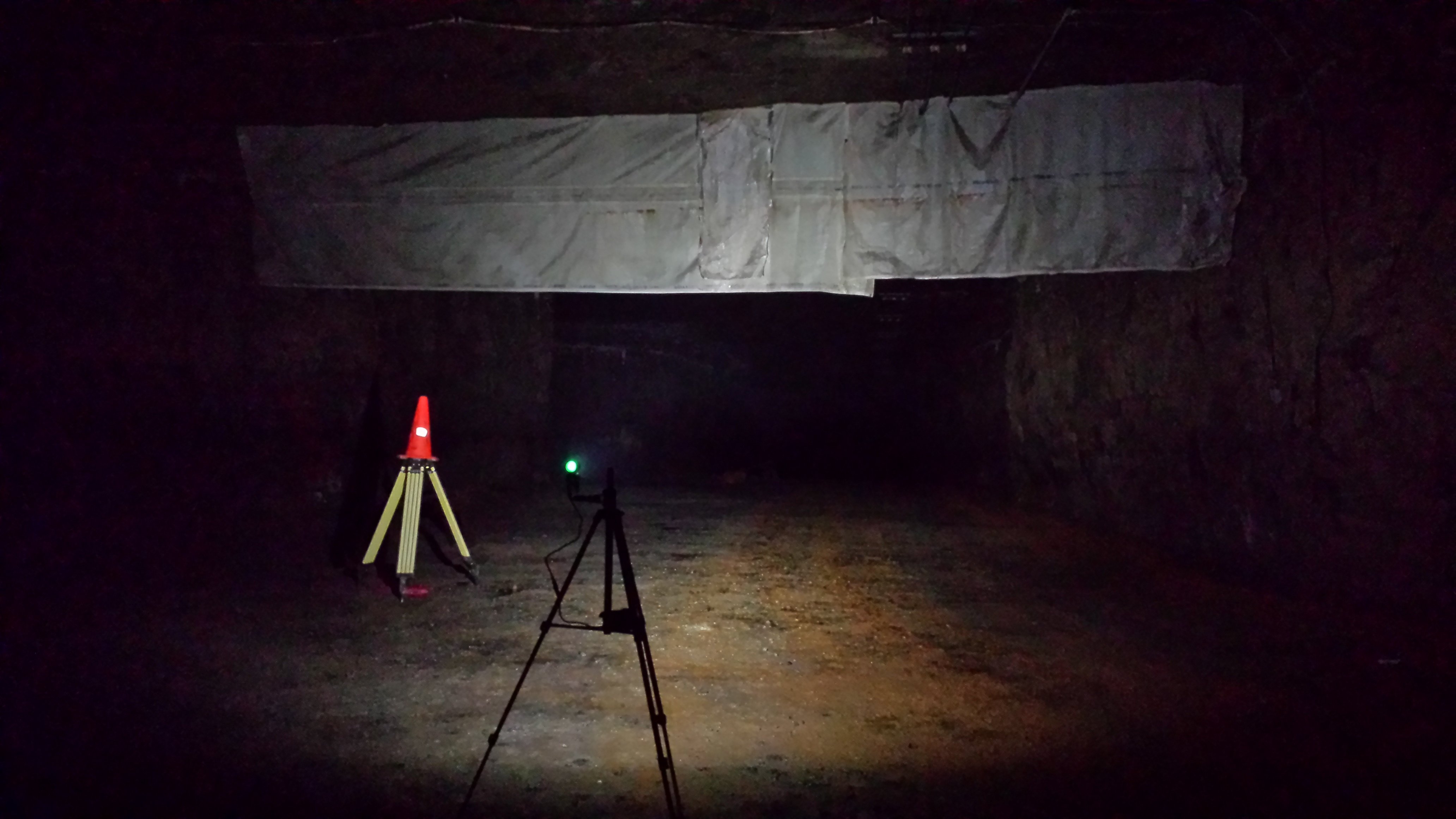
I'll skip the other modes and just show you "Low":
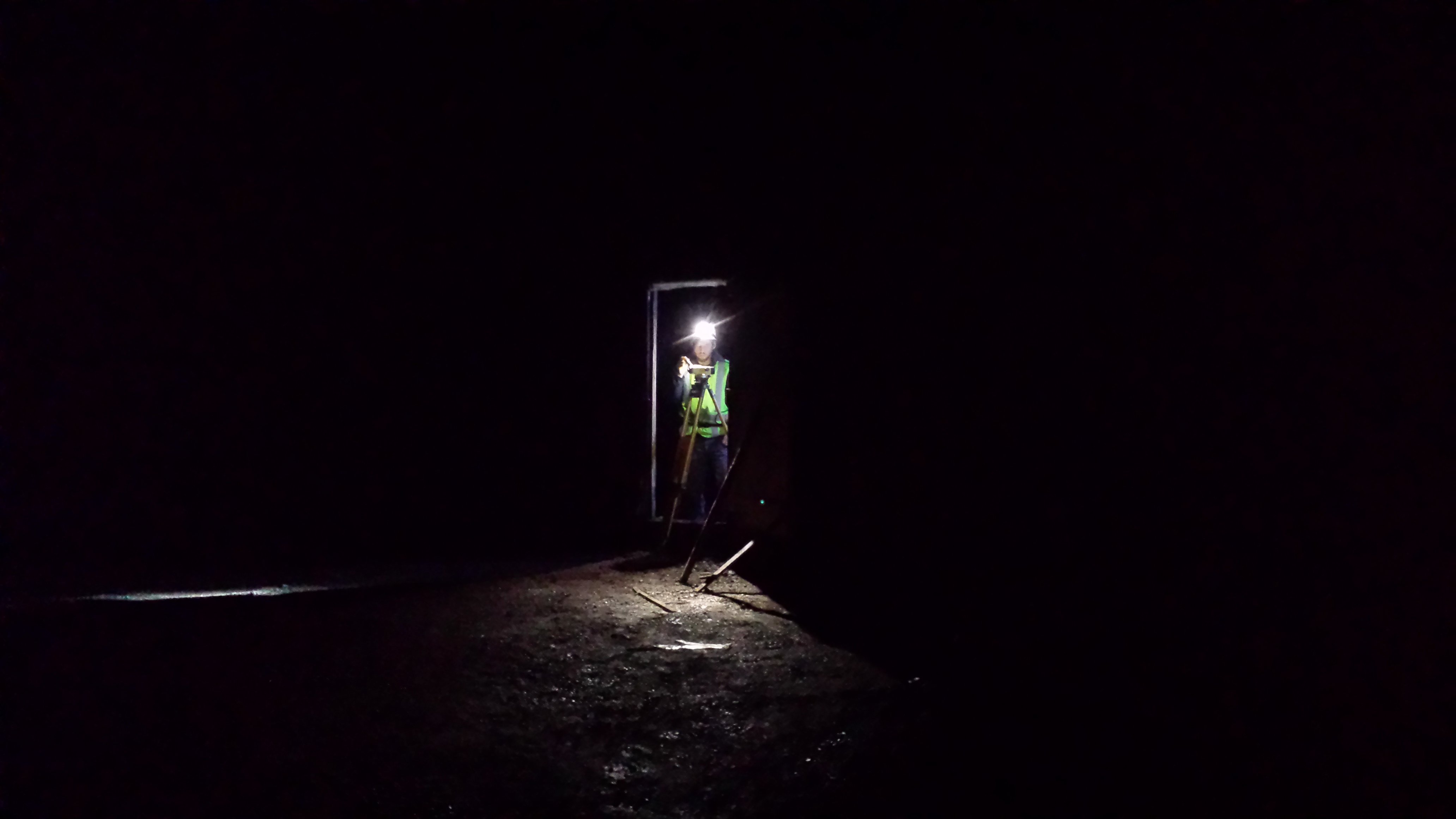
Another random photo looking the other direction at my coworker using one of my headlamps to get setup to work through a doorway.
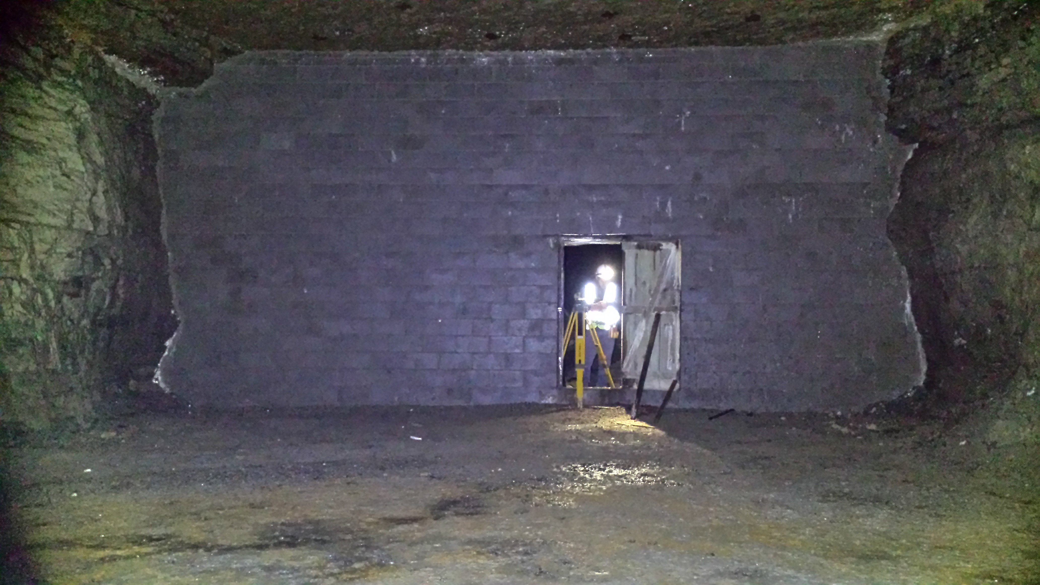
Later on I took a photo using an aspheric flashlight (+/-1,000 lumens) lighting up that whole wall (slightly different angle but same area as above pic).
-Garry