I just received mine and i was quite amazed to see that the centering ring for the xml-2 led is the same Convoy uses in their flashlights, although it seems a bit thinner at the bottom, anyways this is a good thing because i have XPL centering rings from Simon on the way so they would help focusing that xpg-2 that is going in the B158.
I will do measurement again and will take pics. It really jumps high but it settles at lower A after 2-3 seconds. I will show result again when I fill up NCR PF.
I'm not too happy with the current jumping up and down in my measurement above, with the thick copper wires I do not get a good enough contact for a stable current.
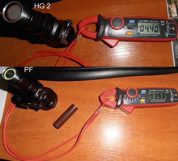
Yes. I measured again with uni-t ut210E clamp meter.
LG HG2 (brown), Panasonic ncr PF (green). Both charged to 4.25V.
This clamp meter has a bit of jump than it settles on real readings. Silicone 12AWG high strand wire used with tinned ends(maybe I should leave exposed wire for better contact?)
So HG2 has 4.4A while NCR PF has 3.9A readings.
I will mention that this was taken with savage finger press on battery - and exposed aluminum at the end of flashlight tube. Since this meter has hold function my wife pressed it :)
Also if you will gently press you will get even lower readings than that. Interesting... Gentle press low A readings, savage press higher readings.
Maybe all that means that solid + - contact(firmly pressed battery inside flashlight) also has some influence on current draw? I don't know.
This stands to reason since contact area and total number of contact points will definitely affect the contact resistance. I would think that well mated surfaces would be more influential than just pressure alone.
There's a couple of factors from my experiences. For my test leads that simply have solder blobs at the end, I refresh the solder on occasion and get higher amps. I've also found NO-OX-ID treatment on the solder blobs will sometimes bump readings, or stabilize the readings. In addition, sometimes a heavy wire jumper from batt- to the body tube gets lower lumens measurements than a fully bypassed tailcap assembled on the light. So, there are issues in contact surfaces.
Heat the end of your jumper till the solder melts, then mash it flat quickly with a screwdriver blade. Gives you a lot more strands in contact with the flat battery end and hopefully more current flow. Not sure what to do with the body end as each light will be a bit different.
I told ya! I wasn’t exaggerating when I said they have the nicest customer service rep I’ve ever dealt with. I’m talking USA too. They sent me a personalized Christmas email when it had been more than a month than I had talked to anyone there. I guess the key is having the right email address. If anyone ever wanted the email just shoot me a PM and I’ll pass it along.
I finally started on my B158 last night. I’m a big fan so far. I did a gas-dedomed XP-G2 S2 1D from FT and the tint came out really nice. Also a FET+1 driver of course. Just by the unscientific measurement of pointing both hotspots at a wall from 15ft and comparing, the throw seems quite a bit better than my Jacob A60 with the same specs. That’s before it’s even done. I still have to install the lighted tailcap and bypass the tail spring, center the emitter (it’s pretty far off center right now), and paint the pill-top black to cut down some of the ugly reflections. I’ll have to measure amps after the Clamp Meter GB comes through.
Did everyone else use the white plastic centering ring or just get rid of it? I am using it for now, just to hold the emitter down.
I also use white centering ring off course. It is far easier to put a dab of artic silver under led mcpcb than to solder to pill and then you see it is a just bit off center. No difference in performance in my book and I tried both.
Yeah I don’t like semi/permanent thermal glues either, I normally use Ceramique II. I just didn’t know if that ring was causing some of the beam “blemishes” since it sticks up above the emitter.
I have soldered the board to the pill btw. Before heating, I used two pieces of a match between board and side of the pill to keep the board centered while the solder melted.

 .
.