@mattlward
You had asked (elsewhere) about designing the ears for your board in Eagle and I think the answer (and perhaps further discussion) is best placed here.
.
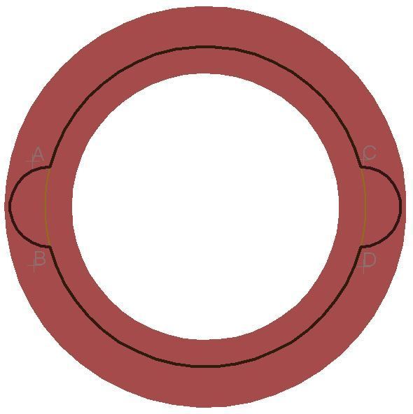
I’d try 4 Arcs (the icon below Text, above Polygon)
Points A, B, C and D are the points where the Arcs meet.
Start with a guiding line (circle, layer 19Unrouted) the size of your board without the ears.
First ear:
Start with the ear on the left, 1 Arc, layer 20Dimension, halfcircle from A to B, the ends have same x-value (they are on a vertical line)
Adapt the distance A to B to your need, keep a halfcircle of 180°, keep A and B symmetrical to the center of the guiding circle
Second ear:
Copy the ear, rightclick to flip, place this ear to the right, the ends on the guiding circle (on C and D).
C has the same y-value as A (they are on a horizontal line). Same for D and B.
Upper Arc:
layer 20Dimension, start Arc at point A, pull to D (you get a circle on the guiding circle), 1st leftclick.
Then pull back to C, the Arc stays on the guiding circle and only gets smaller, a 2nd leftclick sets the Arc.
Lower Arc:
Copy upper arc, rightclick to flip, place from B to D.
Add layer1 and you get something like this. I wouldn’t guarantee that Oshpark produces this result, but I think on the BLF SRK FET driver with its rectangular “ears” it did work out well. In theory Oshpark cuts out everything outside the dimension layer.
.
Hint: If you want to (only) modify the curve of the Arc (or a Wire), hold Ctrl and then leftclick the Arc/Wire and move