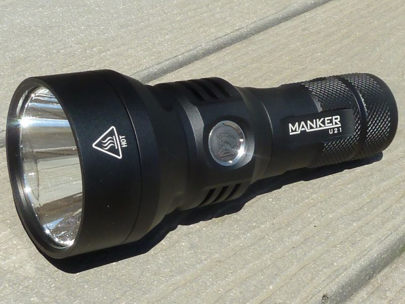
This is a review of the recently released Manker U21, an XHP35 HI based small thrower. Manker provided the light for review, but did realize they sent me an engineering prototype, so it does have a couple of quirks/bugs in the driver firmware that have been since corrected in production. A "small thrower" is a good description of this light, because it's quite a decent stock thrower for a single cell, mid-size stock light.
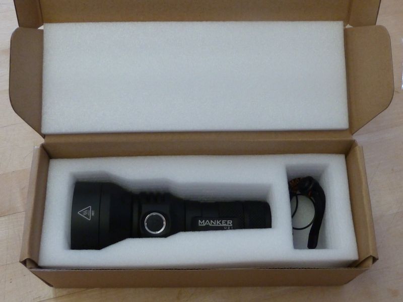
Here's a quick look. Well packaged, light in perfect condition:
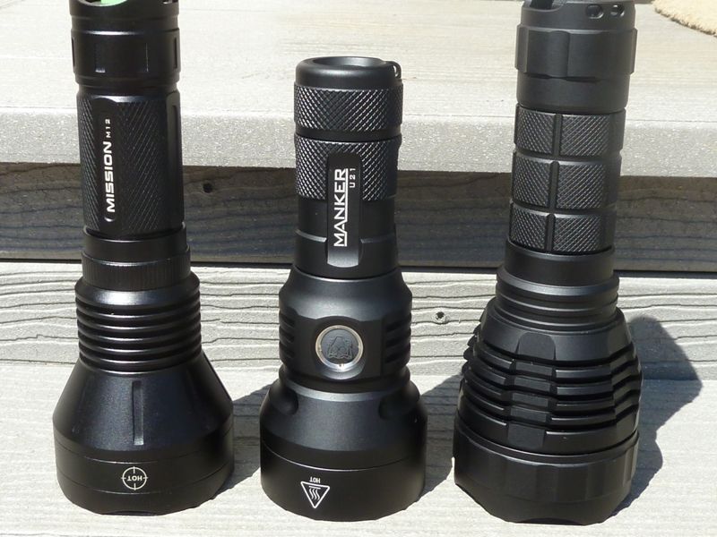
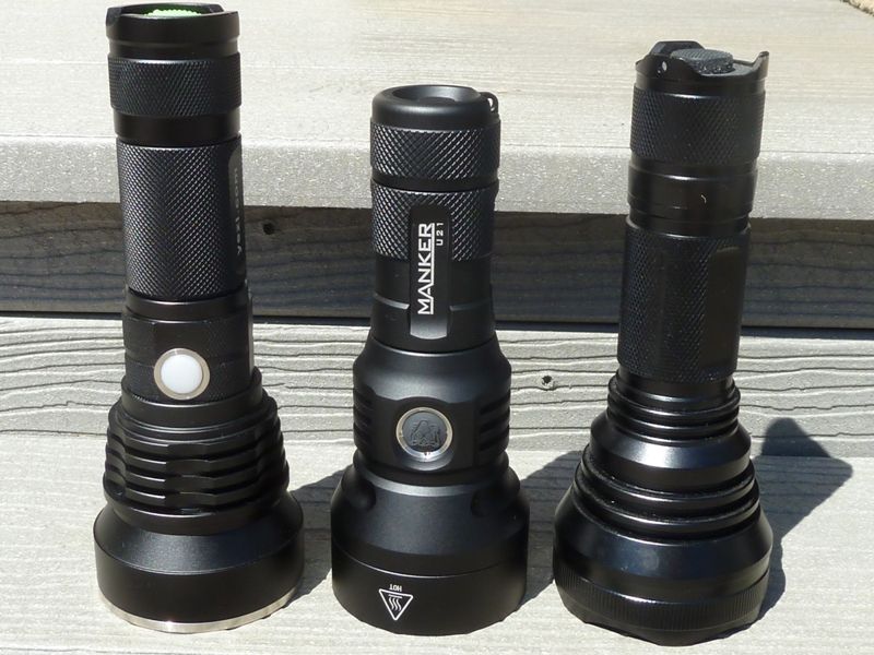
Comparing the U21 to other familiar, similar lights. First, good quality single 26650 throwers, a Maxtoch Mission M12 and the Convoy L2:
More budget but popular single 26650 throwers, Yezl Y3 and the HD2010:
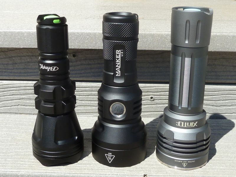
Slighter smaller head diameters, a very good performing aspheric, the Brinyte B158, and the classic XintTD X3:
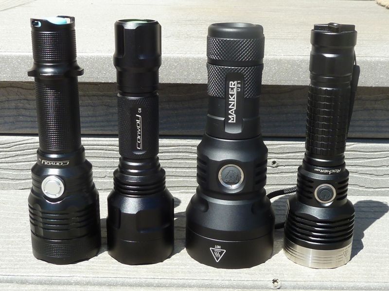
Some C8 size lights to show comparative size, a Convoy L4, Convoy C8, and a Rocher AS31:
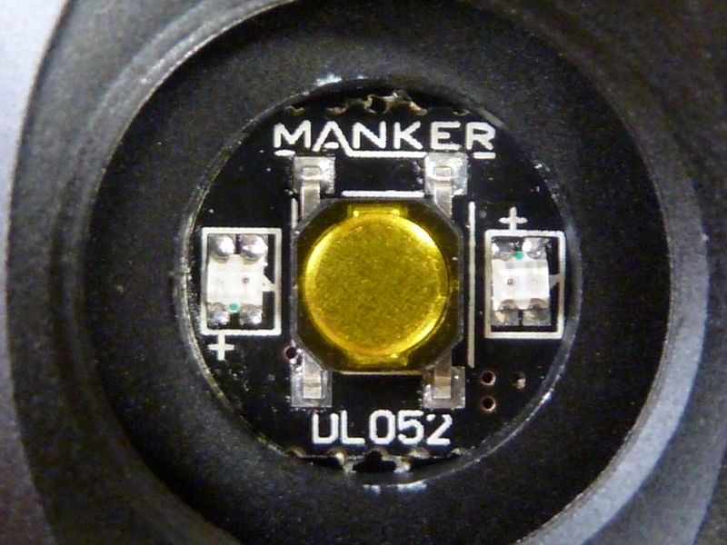
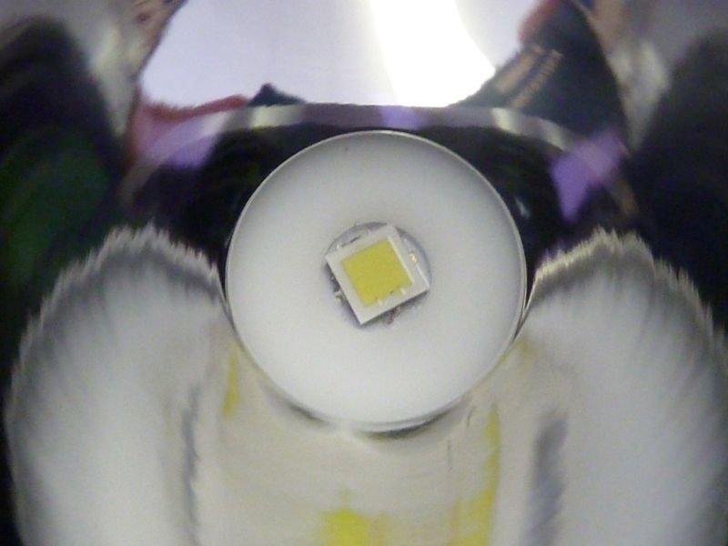
Well centered LED, CREE XHP 35 HI in 6500K tint:
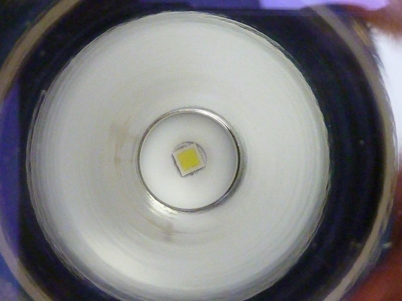
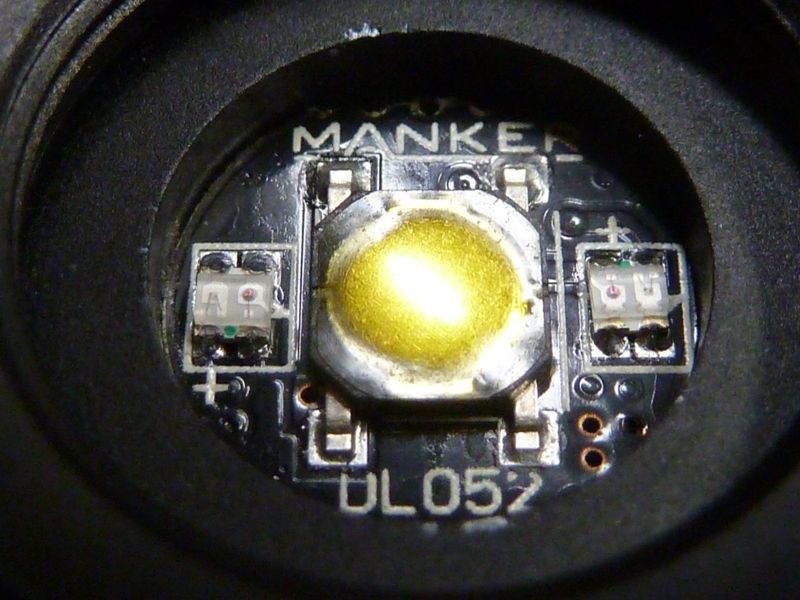
You can notice the purple AR tint here:
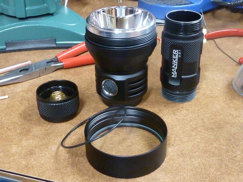
Broken down - tailcap threads were lightly lubed properly, but the connection of the body tube to head was bone dry:
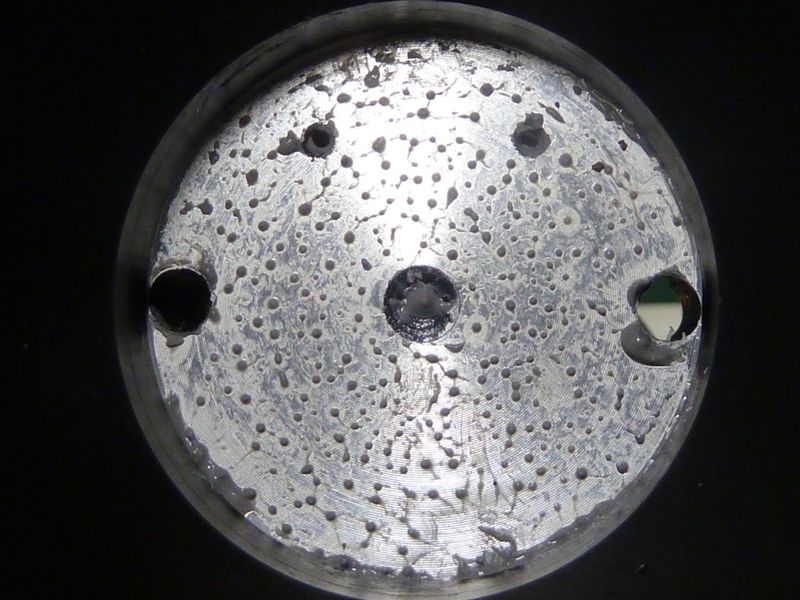
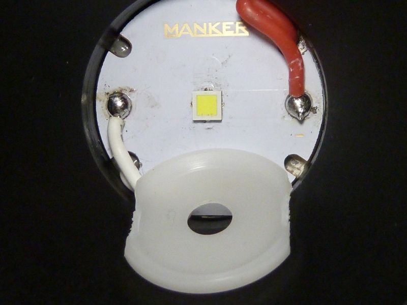
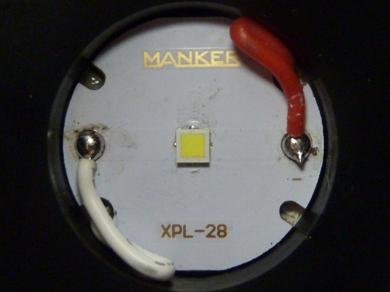
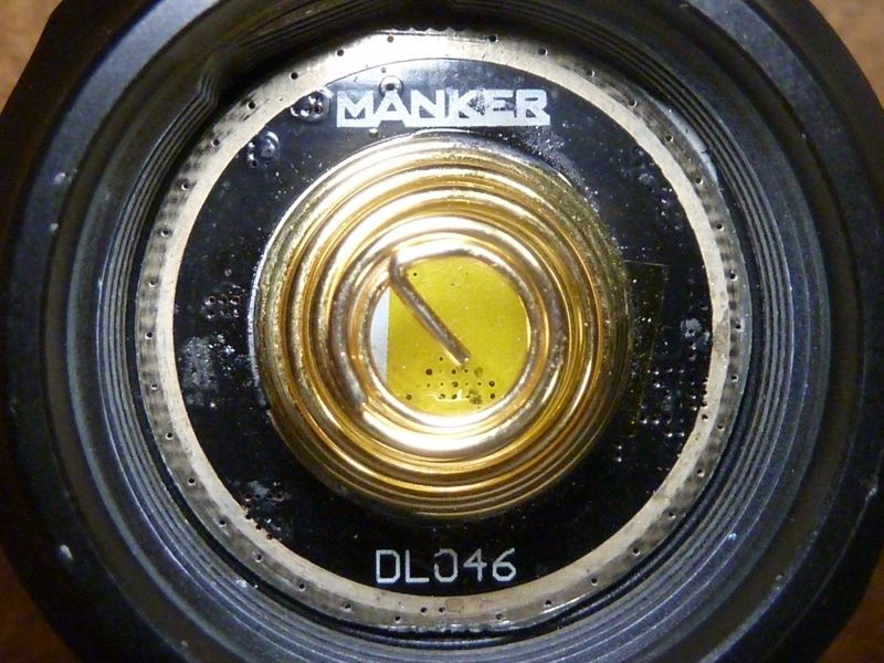
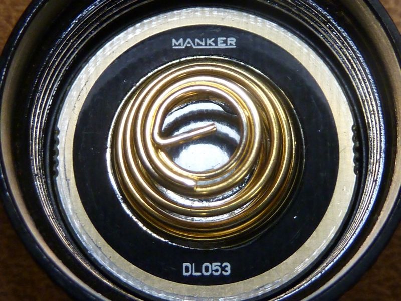
Bezel removed, view of LED/MCPCB. MCPCB appears to copper, not sure if it's DTP, but is a full 28 mm, thermal grease below it, appears to be a solid uni-body style shelf:
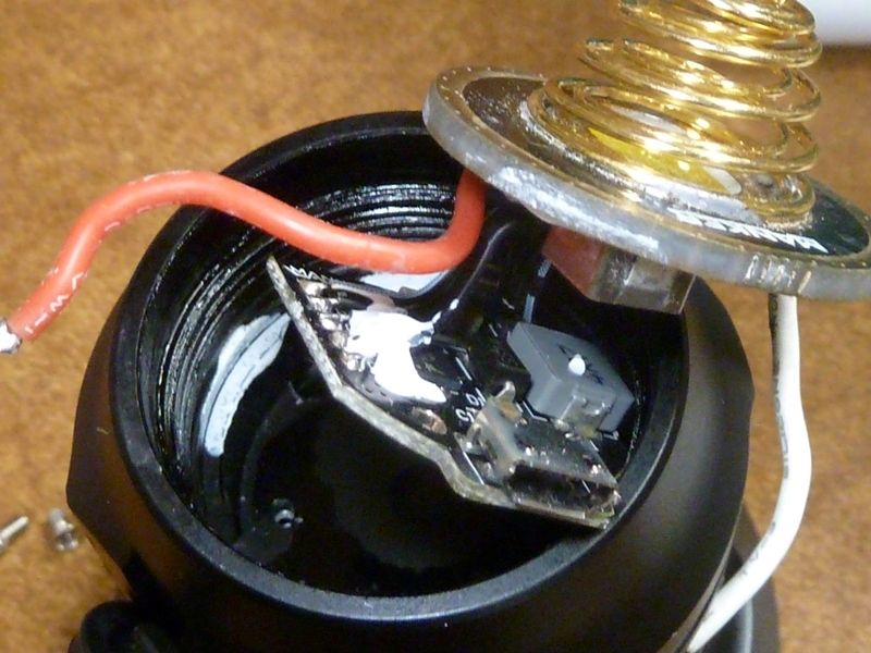
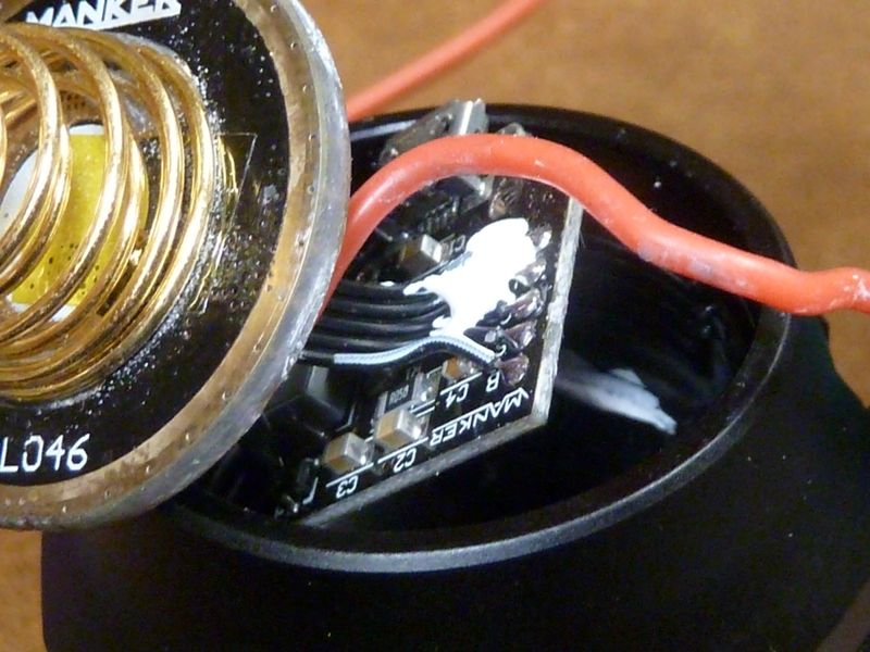
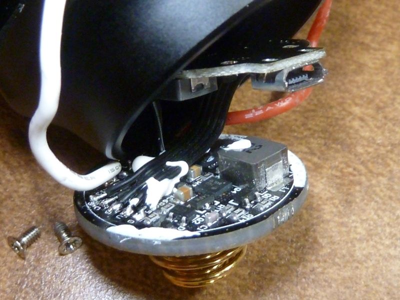
Driver is "glued", probably thermal epoxy. It's a soft type of epoxy, so probably can be broken relatively easy. I'm not sure of the purpose of the kapton tape under the springs. Double springs here on the driver, as well in the tailcap:
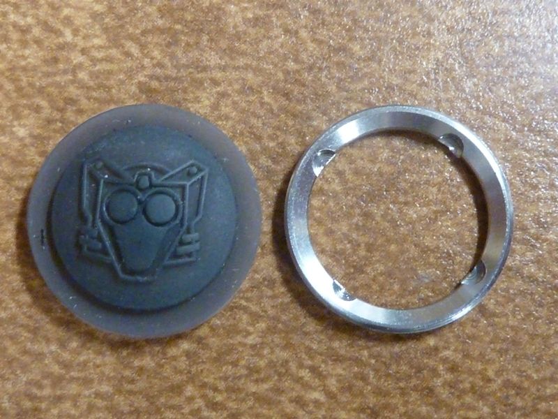
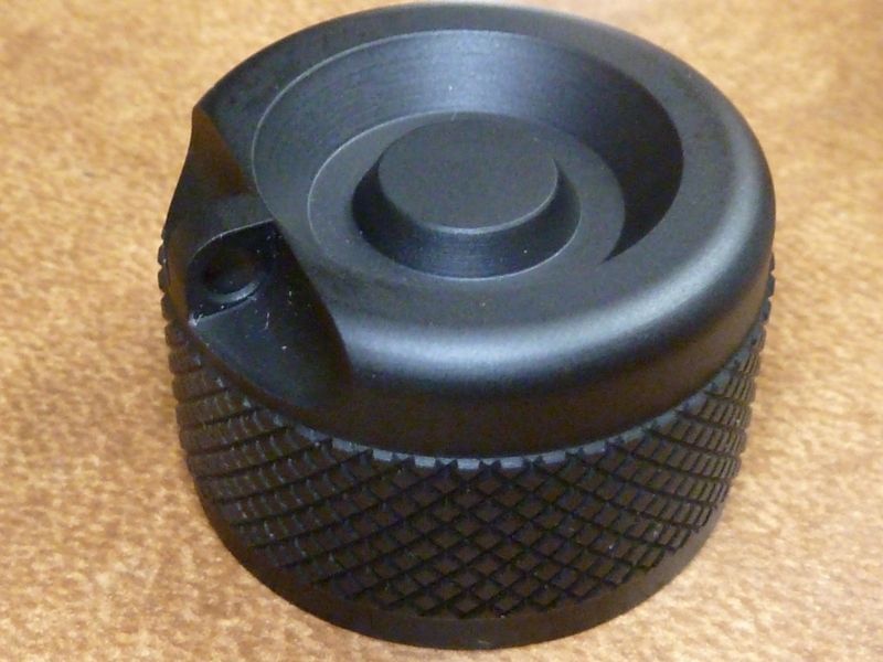
End cap - low profile without a switch:
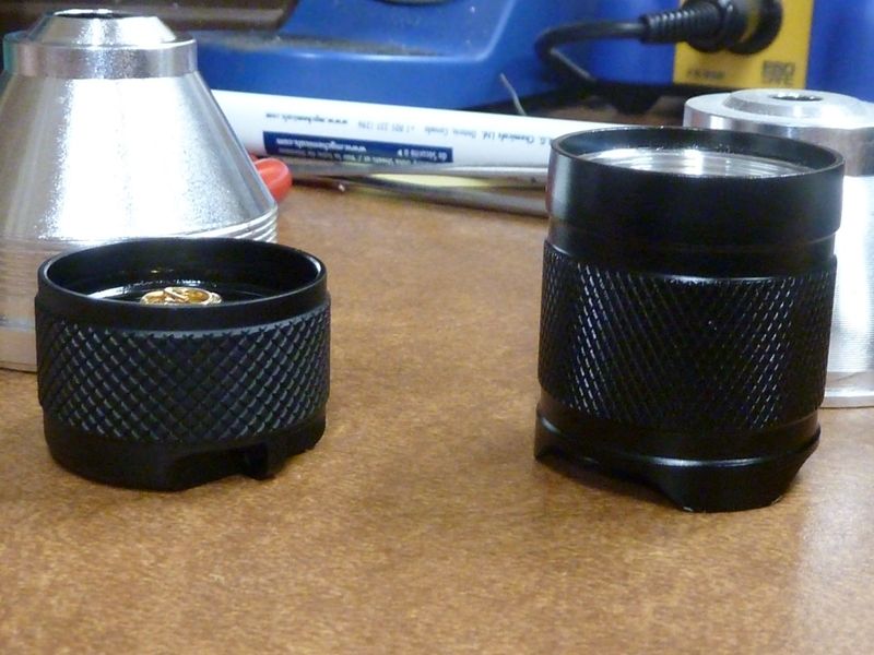
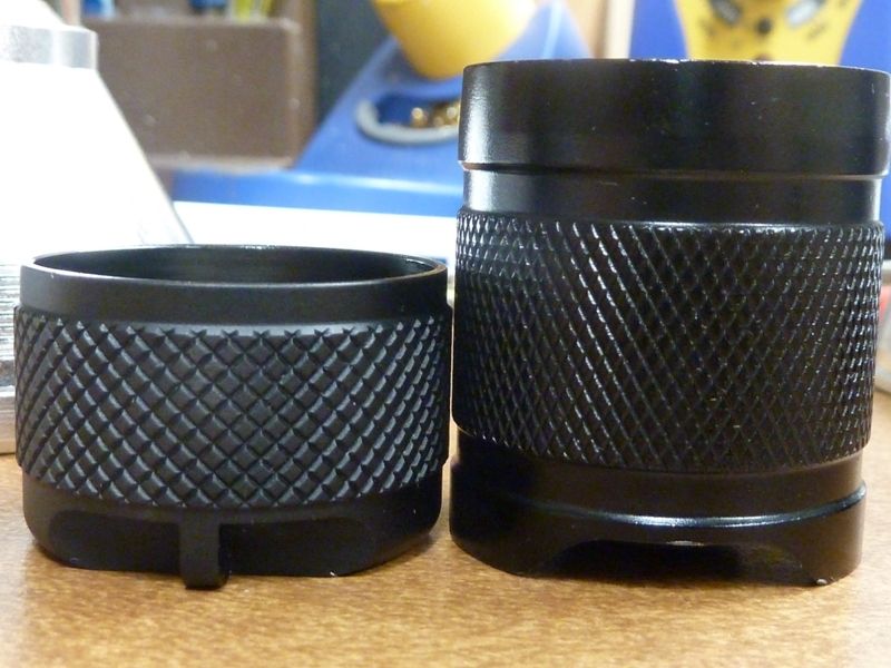
The tailcap of the U21 compared to a HD2010 (on right):
Here are the tailcap springs, also double springs. The PCB also appears to be glued (epoxied) down:
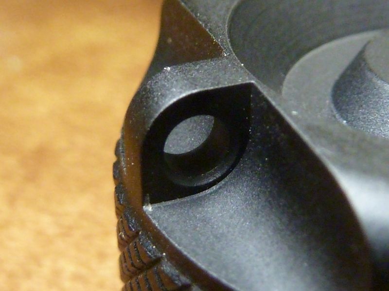
The loop for the lanyard is about the only spot on the outer shell that has a somewhat sharp edge. I've seen this on other not-so-budget lights as well, and it's prone to be a wear point - anodizing layer can wear off. The rest of the light has mostly smooth edges, exceptions being where the heat fins end, by the switch.
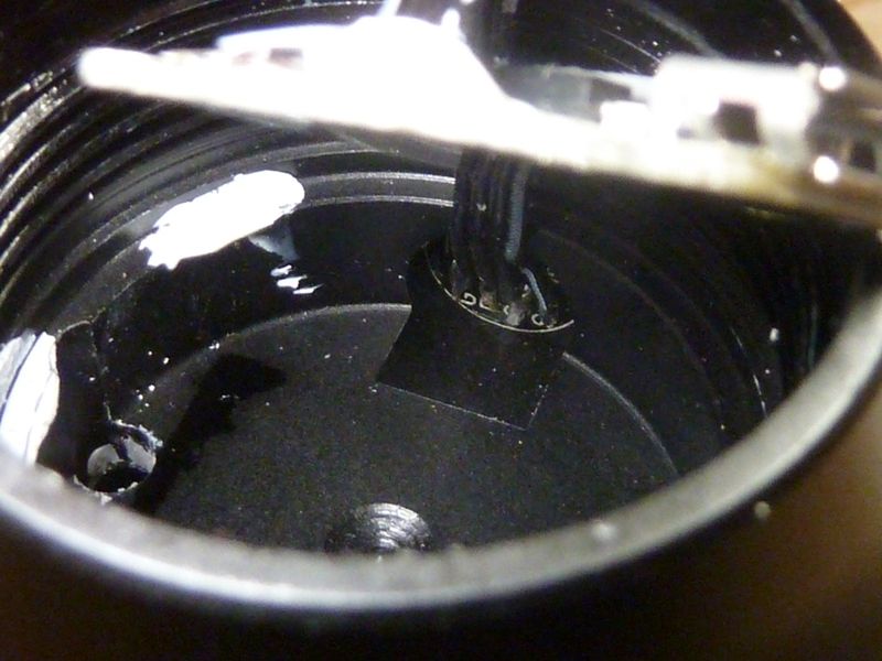
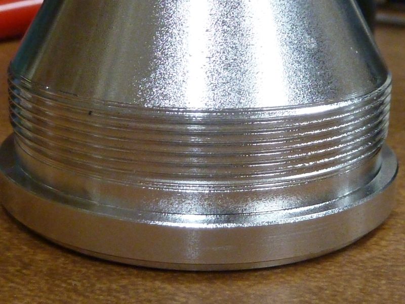
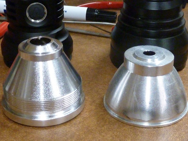
There are nice aspects of this reflector: narrow lip around the hole to allow large LED wires, and nice threading for a tight fit, and thermally conductive to the head:
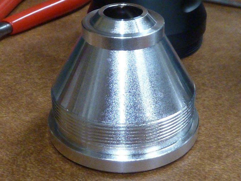
Very nice threading:
Reflector compared to a HD2010 (on right). Though a HD2010's head diameter is 4 mm's bigger, the inner diameter (I.D.) of the HD2010 is only slightly large (~1 mm).
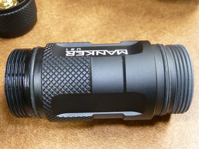
Battery tube. Great finish quality, like the rest of the light, smooth-style knurling. The light feels comfortable in the hand:
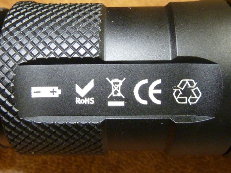
Several symbolics, interesting they got them all in one place:
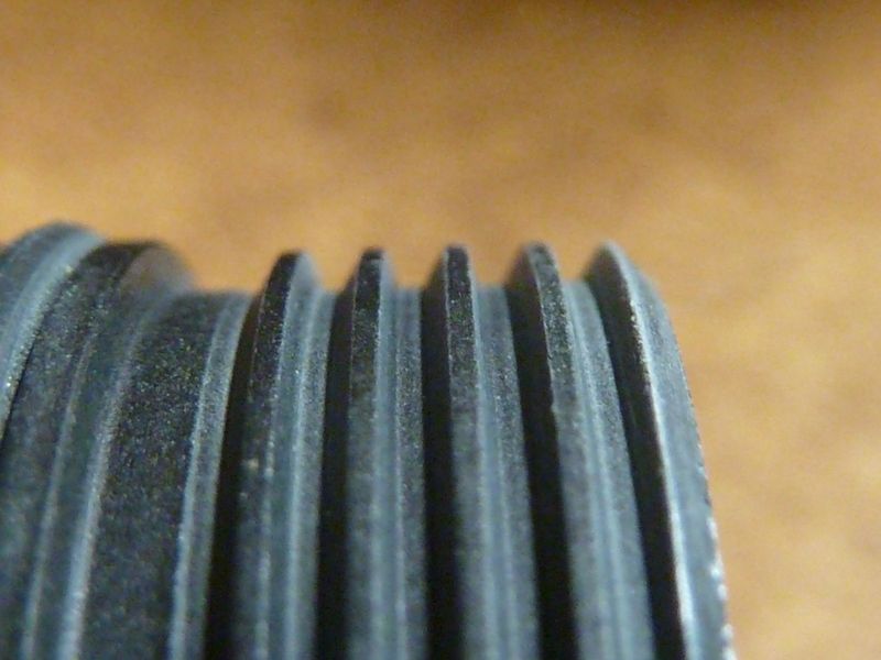
Threads on the tail end of the battery tube - excellent square shape, good # of them too:
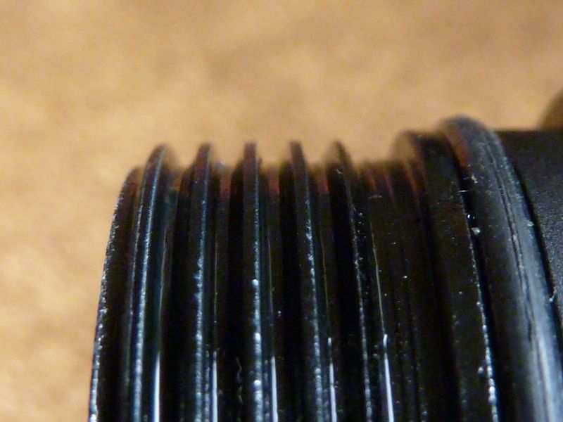
Threads on the head end of the battery tube. Dry, but excellent square shape and quality:
Manufacturer's Specifications:
- XPH35 HI, 1A tint (6500K)
- Driver: PFM/PWM Synchronous booster intelligent conversion circuit
- Type III Hard Anodized (HA III), greater than 50 μm
- must use unprotected or high drain cells (26650 or 18650)
- working voltage: 2.8v - 4.35v
- USB Charging: 2A
- IPX-7, waterproof to 1 meter
- dimensions: 148 mm (length) x 59 mm (head) x 35 mm (tube/tail)
- weight: 290 g, no battery
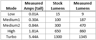
Measurements*
* for amps, a UNI-T UT50B with heavy gauge leads was used, and confirmed against a UNI-T UT210E clamp meter. For lumens, a PCV based lightbox was used (many, many lights tests, and several NEMA/FL-1 rated lights used for calibration), readings recorded after 30 secs.
* an EFEST 5200 IMR unprotected cell was used for testing. Other cells were used to corroborate the readings
- the turbo reading remained steady dead-on for the first 30 seconds - this is very rare, almost all lights drop output because of heat or dropping Vf of the cell
- On Turbo, measured 1.08A at the LED (16 AWG patch wire, UT210E clamp meter), and 5.52A at the tail with a EFEST IMR 26650 5200 mAh cell. This kind of makes sense to me.
- Parasitic Drain: 0.008 mA (Locator LED off), measured on two DMM's: a Fluke 79 series II and UNI-T UT50B. This is very low. To put it in perspective, it would take about 71 years to drain a 5000 mAh cell
- Throw: 127 kcd (measured at 5m), 712 meters
- dimensions by caliper: 148.0 mm (length) x 59.0 mm (head) x 35.8 mm (tube/tail)
- Reflector (using a caliper): 55.65 mm O.D., 47.0 mm depth, 50.0 mm I.D. Being a 59.0 mm head, a 50.0 mm I.D. is pretty good. There are several popular head diameter lights in the 63.0 mm range, and there reflector I.D.'s are larger, but the I.D./head diameter ratio either gains or stays even with any light I've compared it with, in regards to head diameter.
- driver (driver PCB w/spring) is 29.8 mm x 2.05 mm
Modes and User Interface (UI)
The diagram in the manual, along with the written steps below, actually explain it quite well. There's been an inclusion of it online, but it's been too small to make out well. I took a picture of the manual page here.
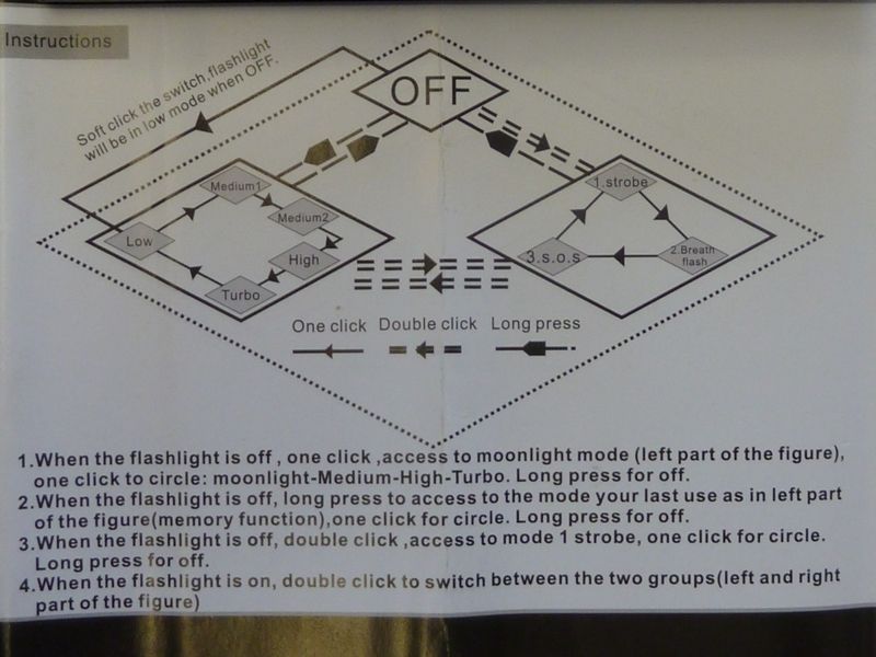
Basically it's a 5 mode light, going from lo to hi, with hidden blinkie modes, though the written instructions leave out a medium mode, and call the low mode - moon mode. Press&hold turns it OFF, and press&hold from OFF returns to last mode used. Dbl-click gets into the blinkies, but "Breath Flash" isn't an output mode at all, actually the main LED is OFF, and the LED in the switch goes into a periodic smooth ramping up, and ramping down. I believe they call it dragon's breath, because the center of the switch is dark, oval shaped, while the LED's get bright, then dim -- it's actually pretty cool, and does look like a dragon or reptile's eye.
You can actually get to "dragon's breath" mode by a dbl-click followed by a click, or triple-click, from OFF or in a regular ON mode.
Downside is there is no direct way to get to turbo, unless it's your last mode used. The dbl-click has to be pretty quick which is good, so it's not so easy to stumble across it unintentionally when single clicking through modes.
USB Charging
There's not a lot of details on how it works, just that it supports up to 2A, and lights up RED while charging, and turns BLUE when done. I've found while charging, you can turn the light ON and OFF by a single click, but in a fixed mode - no mode changing capability.
Runtime - Battery Usage
Generally, you can calculate expected run-times per mode based on the amps draw, as I posted earlier. With this boost driver however, I'm not sure if this is accurate.
When on turbo, after 3 1/2 minutes, output dropped suddenly from over 1,300 to 1,190 lumens, which is above the "hi" mode setting. Repeating the test, is appeared to drop to the same output but closer to 2 1/2 minutes. It appears to be temperature based possibly, not time based (turbo timeout). More testing is needed.
I did monitor the light's temperature on the surface after a few minutes of running, and in 4 minutes it gets warm, but I would not call it excessively warm, not close to being too hot to handle. I don't totally trust my infrared temp gun.
Impressions
Pros
- excellent quality in many respects: anodizing/finish, mark and nick free, design, looks
- compact size for a thrower
- the button is recessed to prevent accidental activation
- simple lock-out by slight twist of the tail
- the looks are impressive with the moderate heat sink finning
- nice having USB charging (one simple test - works as listed)
- excellent performance for output and throw for a stock light of this size
- 5 modes is a plus, fairly easy-to-use UI, with an intense strobe as well
- an advanced boost driver that appears to be quite efficient, compared to older driver designs
Cons:
- price - well for BudgetLightForum, it's a bit on the high side of the budget world. Of course $40-$45 would be a super deal on this light, but still as many suggested, it would be great to get a better deal/price on this.
- modding/repair - the epoxied driver and apparent PCB board in the tail are potential problems.I'm sorry to see such a well made quality light making it difficult for maintenance, repair, and modding. Retaining rings would be the perfect fix for this.
- lack of a moon mode
- UI requiring press&hold for normal operation, like to shut the light OFF
- sharp edges on the loop for the lanyard (minor issue, common on other quality lights)
Reference Links
- Manker U21 intro thread: Small thrower Manker U21 is coming soon
- Manufacturer's U21 product listing: http://mankerlight.com/index.php/en/products/20
- Purchase on Amazon: https://www.amazon.com/Emitter-battery-Distance-Charging-Flashlight/dp/B01G526CE4
- Purchase on AliExpress: http://www.aliexpress.com/store/product/MANKER-U21
- Purchase on eBay: http://www.ebay.com/itm/MANKER-U21
- GearBest? Well, maybe a placeholder: http://www.gearbest.com/led-flashlights/pp_368080.html
- Review of the U21 by Budda: Review of Manker U21 - 18650/26650
- Review by bugsy36: Review: Manker U21 - Raising the bar for compact throwers