
This may sound like a bit of a jumble but thats the way my mind is at the moment with the latest update from Justin.
http://dyingintylertx.blogspot.com.au/
Justin has a wish for two different lights that he would love to have built for sale to the general public.
One was from memory, an XHP70 led, RMM built driver, LUM 5-90 reflector and 2S 4P battery configuration (think I have that around the right way. Richard has been trying to educate me). A Flash Light Lens lens will also be used.
This light will be my interpretation of these specs using techniques that Justin may use and my own abilities, or lack of to build this light. ![]()
There is no time frame to this build and I’ll update it as needed.
The first change to the spec is I will more than likely use a battery configuration of 3S 3P. The reason for this is so that a higher current can be kept up to the led for a constant output for a longer period. The XHP70 is voltage hungry the harder it is driven
Thanks to the testing by djozz we can see here that the XHP70 needs nearly eleven volts at 10 amps. Post 576.
I’ve roped Richard in to build me a driver and so far he has been exceptionally patient with my inability to describe to him what I want. I was thinking of getting RBD to decipher my lack of correct descriptions to Richard as he is a gun at being able to do that, thanks RBD for the help in the past, but I think we have got there now. It does worry me though as I have not heard from him. Richard, in the last ten minutes. ![]()
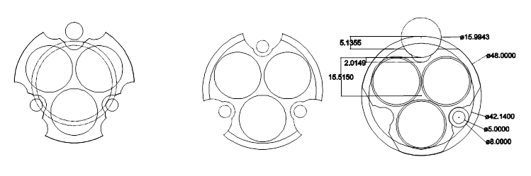
This is the type of information that Richard has been deciphering.
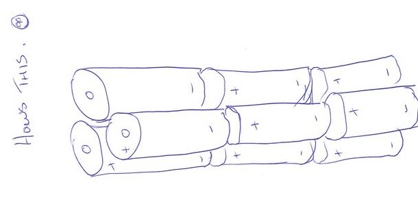
The battery configuration was a bit of a dilemma for awhile with lots of drawings happening to try and work out what would be best with spacing etc. I also tossed up with the idea of using a battery carrier but at this point probably wont.
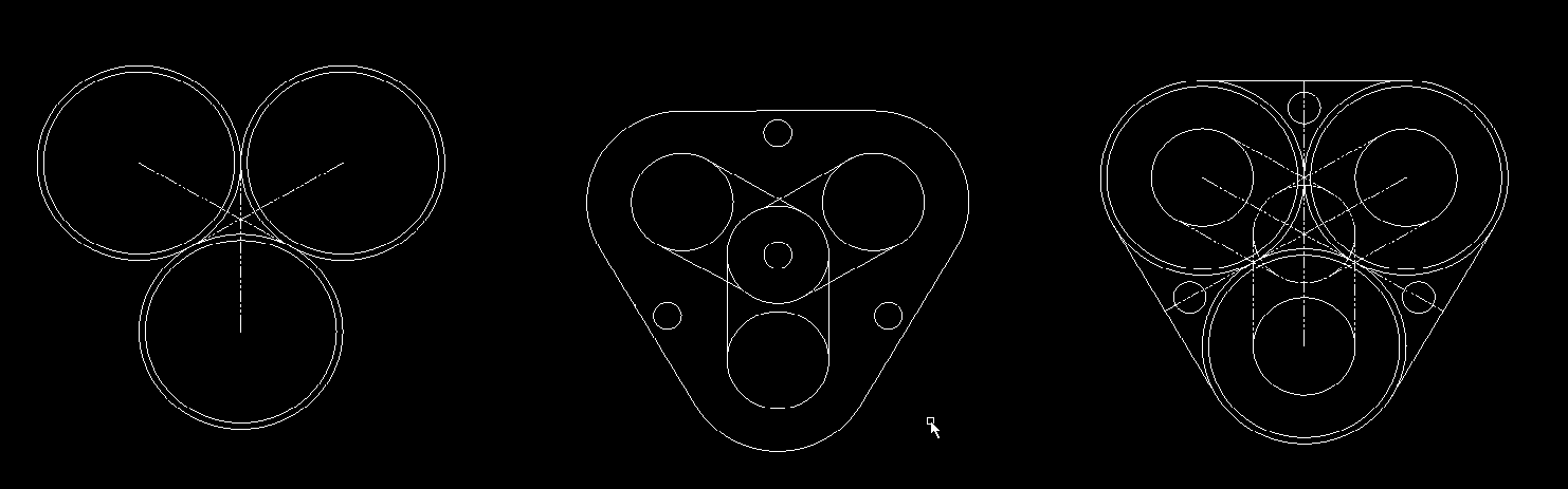

The deign of the light is almost complete as can be seen below. As you can see theres lots of work still to be carried out. :person_facepalming: I’m sure most of you know what DNF stands for. Please dont ask my lovely wife. ![]()

Todays update 27.6.16.
The cover was pulled of the power hacksaw, the oil can put to use and the 2’’ bar stock was cut to length.

These were faced off and turned to 50mm in diameter from 2’’ as the finish was not that good.

As the battery tube will be drilled out on the lathe held in the four jaw chuck to allow for the offset a way of marking out the three holes had to be made. This is a sleeve that will slide over the end of the battery tube to mark out the battery location holes.

The three holes were accuratlye machined in the mill. Why did I not use the mill to machine the battery holes or just mark them out? Simple, its not big enough, limited in height and travel.

The drill used to drill the holes in the jig was sharpened on the shank end to a point.

And used to centre pop the holes in the battery tube.

Normally when i build a light from scratch I build the head first then the tailcap and finally the battery tube. As the head cannot be built until I know what driver is going in the battery tubes are being machined first. My first backward built light. ![]()
Update 5.7.16.
Just a little explanation on how the holes in the battery tube were marked out and positioned in the lathe.
The original jig I made was for 50mm diameter bar which two battery tubes are. When I screwed up the other two I decided to make them again from 60mm diameter bar.
How to use the same jig? Wrap the two items together with a piece of A4 paper with the jig upside down and mark the holes.

This leaves you with the end of the work piece with three holes marked out on it.

This is then placed in the four jaw chuck in the split tube made previously to prevent damage and the jaws moved around until the hole lines up with the centre. Most times when the lathe is switched on the centre pop is running out slightly so adjustments are made until the centre pop does not run out.
You can see how far offset the work piece is by looking at the jaws of the chuck. This will be repeated another eleven times to do all four battery tubes.

Heres two that were prepared earlier. I just wanted to add a bit of cooking speak in. ![]()

Update 19.7.16.
Lifes been busy around the house lately so work has progressed slowly.
The four battery tubes have now all been bored so the next step was to build the negative end plates. With some input from Justin the following is the result.
Copper was chosen as the springs could be soldered to it and I just happened to have an off cut of 1 1/2’’ waiting to be used up.
A spot face was machined in three places to locate the djozz springs that will be used in the correct positions.

Not having a 10mm slot mill to machine the spot faces a1/4’’ slot mill was used to machine the depth to 30 thou and then a 10mm drill bit ground flat, was used to finish of the spot faces.

To locate the end plate in the battery tube in the correct position 1/8’’ brass rod was deemed suitable to be used as guides. These will also be soldered into the end plate’s. 3mm holes were drilled into the end plates for these locating dowels.

The nearly finished being machined end plates.

The 1/8’’ dowels themselves being machined up.

And finally for this update an end plate with the locating dowels.

Update 8.8.16.
Things have been a little slow on this light lately after I made a mistake on the engineering in the way I was going to join the battery tubes together, bolt pattern and the pin locator holes for the negative plate. This will be rectified by remaking the negative plates from a larger diameter material so the dowel PCB will be the same as the through holes to join the two battery tubes together and will be around 8mm in diameter instead of the 1/8’’ as originally planned as the cap screws, which I dont have yet, trying to find them cheaper, have a head diameter of 8mm.
Hope that all made sense.
The new plate against the old negative plate.

To drill the holes out for the through bolts and negative plate dowels I set the battery tube up clamped to a v block and tried to use my dial indicator to get two holes parallel. I was just not happy as I could not get consistent readings, though admittedly it was only by a few thousands of an inch.
Not one to normally purchase cheap tooling the purse strings at the moment only allowed me to buy the cheapest test dial indicator I could find. Its on its way from China so hopefully it will do what I want it to.
The set up.

Meanwhile back on the PC I’ve been messing around with ideas on what shape it should be. I have decided on one now to see if I can make it happen.
Updates to the build.
Post 48 and down a couple.
Post 87.
Post 98.
Post 105.
Post 117.
Post 120.
Post 128.
Post 136
Post 149
Post 184
Post 188
 , but of tears joy and then a big
  .
.