[Oshpark] BLF SRK FET v3 (46mm / LFPAK56 / Dual+Triple Channel / ATtiny13A+85)

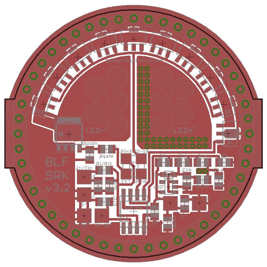
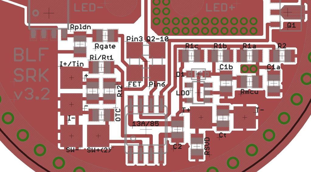
Yes, RMM recommends 20-50 Ohm for the gate resistor, but he kept quiet about the pulldown resistor. I don’t have a scope so I just kept reading what these R are for and how their value should be. This is not as easy as it looks, as both are often referred to as “gate resistor”. And the funniest calculation was this, which the author deemed as minimum knowledge needed about gate circuit resistance in MOSFETs. Well, he lost me at point 1…

So this was my train of thought:

Although frequency does not really matter in my design (no PWM), spikes will in all probability occur at switching. Now I’m not sure which of the two R prevent that, so my intention is to use both.

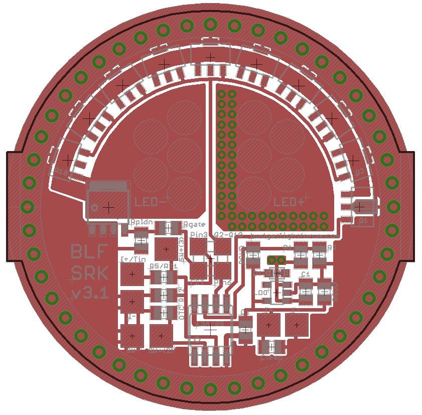
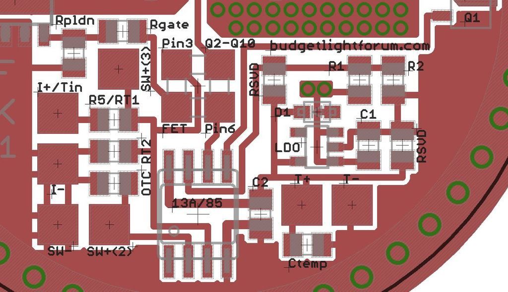
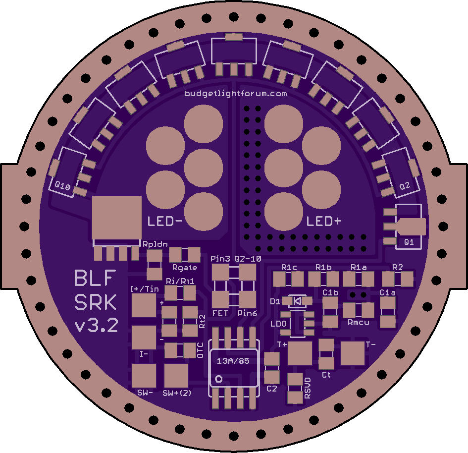
The pulldown resistor is said to be necessary to keep the gate from floating. Values between 1k, 10k and 100k ought to work. BLFers had good testing and scope results in the tens of kOhm, so I used the nearest I had which was 33kOhm.

The (series) gate resistor shall protect the output pin of the MCU by preventing overcurrent. There’s talk of values between 10 and 150 Ohm. I have no such value at hand… Well, the Attinys are said to have overcurrent protection although I couldn’t confirm it. But a lot of BLF FET driver were built without a gate resistor, so I dared to build it with a 0-Ohm-resistor for now. But I plan to use a gate resistor after my next parts order, because it might help preventing spikes, might protect the MCU and will not hurt the output. I thought of 50 Ohm, but I’m open to suggestions.

.

Err, another thing, while we’re talking resistors… R1 and R2 (LVP).
How high can we go to

- keep parasitic drain as low as possible

  • while still get reliable voltage measuring from the MCU?
    With my values of 33k/8k2 (I still prefer behind D1) I measure a parasitic drain at sleep_mode of 0.25mA. Now you use (before D1) 220k/47k for ages and probably with good measuring. One might think of even higher values, like 2M2/470k, 22M/4M7. Is there a limit where the MCU will not be able to measure the voltage anymore? Could that be calculated?

Can't recall, maybe Mike C tried higher values for R1 and R2 - he said what those were, can't recall - hgiher than my 10X though and pretty sure proven to work fine. I used 10X factor because I had them, common sizes. But I also bought limited qty of values bout 3X higher than that, effective cutting the R1/R2 drain by another factor of 3 -- didn't try this yet. Dunno if there is a theoretical limit on the values, but 1M or 2M for R1 sounds familiar think it was tried and worked.

The 13A is well proven to tolerate spikes better than the 25/45/85, so, these gate resistors are probably not needed at all on a 13A, but on the scope, things look much better with them.

More important for reducing parasitic drain than tweaking higher R1/R2 is making a correction in the firmware to shut down the AtoD when goin in sleep mode - forgot the difference but it's big. First recommended by Halo in the 24/45/85 thread - dunno, others might have done this in custom firmware but as far as I know, none of the standard open source versions do it.

I'm seeing 0.007 - 0.009 mA drain in a few stock better lights, so it's done and out there. For me, I just think no one should have a concern about draining the battery simply because it's left in an e-switch flashlight vs. a power switch light.

That’s very helpful, thanks. I’ll look into both.

I’ll change R1/R2 from 33k/8k2 to 330k/82k first, just to see the practical result. In theory it should lower the parasitic drain (@4V) about 0.09mA, pushing it from 0.25mA to 0.16mA. I might try another x10, which would save another 0.009mA, and see if voltage measuring will still work.

Turning off ADC rings a bell. Found it again in post #2 of Toykeepers Firmware repository. She mentions @Crux:
Investigate, measure, and document ultra-low-power sleep modes. Crux’s posts here and here, ideas here (link is external) and here (link is external) and here (link is external)
The firmware I just use has an ADC_off routine, but it’s only called when there is no voltage monitoring. Calling it before starting sleep mode looks easy, but I’ll have to find where to put the ADC_on command to reenable it after a switch press.

But that looks very promising and together might bring the drain down by x100. :slight_smile:

Narsil has the support, so could check there as well, 7/11 version is the latest: Shared project folder on Google Drive

Here's the full function:

/**************************************************************************************
* SleepUntilSwitchPress - only called with the light OFF
* =====================
**************************************************************************************/
void SleepUntilSwitchPress()
{
// This routine takes up a lot of program memory :(

// Turn the WDT off so it doesn't wake us from sleep. Will also ensure interrupts
// are on or we will never wake up.
WDT_off();

ADC_off(); // Save more power -- turn the AtoD OFF

// Need to reset press duration since a button release wasn't recorded
wPressDuration = 0;

// Enable a pin change interrupt to wake us up. However, we have to make sure the switch
// is released otherwise we will wake when the user releases the switch
while (IsPressed()) {
_delay_ms(16);
}
PCINT_on();

//-----------------------------------------
sleep_mode(); // Now go to sleep
//-----------------------------------------
// Alternate method? --> set_sleep_mode(SLEEP_MODE_PWR_DOWN);

// Hey, someone must have pressed the switch!!


PCINT_off(); // Disable pin change interrupt because it's only used to wake us up

ADC_on(); // Turn the AtoD back ON

WDT_on(); // Turn the WDT back on to check for switch presses

} // Go back to main program

Just what I needed :beer:

that should fit in here very nicely

void sleep_until_switch_press() {
    WDT_off();  // Turn the WDT off so it doesn't wake us from sleep
                // Will also ensure interrupts are on or we will never wake up      
    press_duration = 0; // Need to reset press duration since a button release wasn't recorded
    while (is_pressed()) {  // Enable a pin change interrupt to wake us up. However, we have
        _delay_ms(16);      // to make sure the switch is released or we will wake when the user releases it
        }
    PCINT_on();
    sleep_mode();   // Now go to sleep
            // Hey, someone must have pressed the switch!!
    PCINT_off();    // Disable pin change interrupt because it's only used to wake us up
    WDT_on();   // Turn the WDT back on to check for switch presses
}               // Go back to main program

New resistors for R1/R2 aren’t there yet, bit I couldn’t resist changing the code. Just adding the two lines about ADC brought the sleep mode current down from 0.254mA to 0.89mA 0.089mA at 4V. It’s even down to 0.068mA at a more relevant 3V.

That’s so simple and effective, when you know what to do. Again thanks TomE for the hint.

void sleep_until_switch_press() {
    WDT_off();
    ADC_off();     // <++++++++++++++
    press_duration = 0;
    while (is_pressed()) {
        _delay_ms(16);
        }
    PCINT_on();
    sleep_mode();
    PCINT_off();
    ADC_on();     // <++++++++++++++
    WDT_on();
}

.

EDIT Oct 16: The above values were with 33k/8k2 as R1/R2. In the meantime I changed to 330k/82k and that brought the current when off down to 11µA (0.011mA) with a cell that is 3.3V resting. LVP still working as before. Now that’s really good.

Cool! Think there's a typo there on the values?

Yes, sure it is. Ah, these zeroes…
Corrected

Thanks, i just tried it and it works on the tripledown driver with a e-switch :slight_smile:
Finally I can use that driver in my e-switch lights.
Do you think it is possible to add a memory function, so that when power is cut via the clicky switch it remembers the last mode and starts in this mode? This would make it usefull for dual switch lights too.

The more I look at this, the more I'm intrigued and interested. If you could extend the MCU pins to accomodate an 85, that would be great. But besides, the BLF Q8 SRK board has the stock 10 uF C1 and we add a 0.1 uF C2, though. Our C2 has to be close to pins #4 and #8 - I've found it works well with the 25/45/85's. I almost always air wire it across the MCU on stock drivers.

It looks like you got other important things in place, like the RGate and gate pulldown which we are populating. Plus the LDO would be a huge+ over what we have.

We designed ours for FET+1, and using pin #3 for an optional indicator LED. If your driver could accomodate that option as well, it would be right there with ours, but of course, your's can be configured for so much more.

The STAR Momentary firmware does not include any memory options or saving functions, so that part would need to be made up from scratch or transferred from a clicky firmware. I’m really not a firmware guy, but I think it is possible.

.

This can be done.

- ATtiny85,

- C2 closer to MCU,

  • indicator LED to pin3, very well.
    Anything else? :wink:

While I’m already sketching the board…
Could you give me some input, just to know if I might omit options if the space was needed.

- Is the outer diameter of the Q8 board (46.02 mm) enough or would the “ears” of BLF SRK FET still be needed?

- As momentary switch pin2 is most commonly used, is pin3 for the switch an option at all anymore?

- There was talk of a snubber circuit for the FET, is that still in discussion?

- what for are in Q8 (v3) the two small rectangular pads above BATT LED?

  • Is the Zener Diode in Q8 the usual Zener-Mod-Diode and not necessary with an LDO version?

Any feedback is welcome.

Oh boy - not sure if I'm stepping on toes. Yours is a more generic board since it serves many possible options, while ours is more single/special purpose.

- Is the outer diameter of the Q8 board (46.02 mm) enough or would the “ears” of BLF SRK FET still be needed?

The ears would serve well for a generic SRK board that could be used in various/most clones that don't have a retaining ring. Actually I requested it for ours, since our OSHPark BLF Q8 is only gonna be used a prototype, typically in the cheap SRK clones available today. It turns out though we haven't found a need - we can still get a tight press fit, least on the clone I'm using so far.

- As momentary switch pin2 is most commonly used, is pin3 for the switch an option at all anymore?

I'm not aware of it being used on pin #3

- There was talk of a snubber circuit for the FET, is that still in discussion?

Hhhmmm, not sure - can't recall details, but we are not using it at this point, but DEL is going to be scoping our new board, so if he's satisifed, it won't be used or considered I'd think

- what for are in Q8 (v3) the two small rectangular pads above BATT LED?

Ok, that's a good question - I see them, they are there.. Just not sure. Maybe either sets of pads can be used for wiring up a indicator LED, not sure...

- Is the Zener Diode in Q8 the usual Zener-Mod-Diode and not necessary with an LDO version?

No, it's not meant to be the typical zener diode. It was intended to be optional, only if we could not get a stable VCC input to the MCU with the other enhancements. Richard's new MTN17DDm v1.1 uses az ener the same way as our intention, but it doesn't look like we need it. In fact it's not recommended because of the leakage that adds to parasitic drain significantly.

Any updates? Still very interested in the progress, Great Job btw!

Almost done. Just finetuning.

BLF SRK FET v3.1
.

EDIT: I just saw the results @DEL posted in the Q8 thread. As further alterations in the circuit seem to be useful, I removed the link for now, await the progress with excitement, and you may see the following as an intermediate state.

.

.

.

.

:slight_smile:

BLF SRK FET v3.2

.

Changelog (from v3.0)

- combined ATtiny 13A/85 footprint

- added support for battery indication LED (I+/I-/R5/±)

- moved C2 closer to MCU

- added Rmcu to reduce ringing

- added multiple spots for C1 and R1

- increased GND path to FET

- increased amount of GND vias

- increased amount of LED+ vias

- added thermals for AMC7135s

- slightly larger GND pads for AMC7135s

- removed star-pads

- removed snubber pads

  • removed SW+(3)

.

Oshpark Link

.

.

.

.

.

.

Partlist

- 13A/85: MCU ATtiny13A or 25/45/85; 8S1 (SSU) or 8S2 (20SU)

- Rmcu: Series resistor between VCC and MCU Pin1; 0805

- FET: N-Channel MOSFET at Pin3 or Pin6; LFPAK56

- Rgate: Series gate resistor; 0805

- Rpldn: Pulldown resistor (gate to GND); 0805

- Q1: Single AMC7135 at Pin5; SOT-89

- Q2-10: Up to 9 AMC7135 at Pin3 or Pin6; SOT-89

- D1: Schottky diode (~0.25V) for 1S (4.2V); SOD-323

- LDO: Low dropout regulator for 2S (8.4V) [LDO needs C1 and C2]; SOT-23-5 (Vout is pin5)

- C1: Cin [before Rmcu (C1a) or behind Rmcu (C1b)]; 0805

- C2: Decoupling capacitor for MCU; 0805

- R1: Voltage divider to VCC [before Rmcu (R1a), before D1 (R1b) or behind D1 (R1c)]; 0805

- R2: Voltage divider to GND; 0805

- SW+(2): Pad for momentary switch to Pin2

- SW-: Pad for momentary switch to GND

- Tin/Rt1/Rt2/T+/T-/Ct: Temperature sensor

  • I+/I-/Ri/±: Indicator LED

.

Happy modding :slight_smile:

I missed this some how. This V3.2 version is looking really good. I like the pin wiring options. I have a triple version of Narsil posted - been testing it and seems to work pretty well.

Full source here: https://drive.google.com NarsilTriple v1-2.zip

Thanks for the code!
Triple channel is so awesome. It eats a lot of pins, but it eliminates almost all disadvantages of a FET driver.
I was still testing and adjusting v 3.0 in my 7x SRK (a 1A-4D-7A multi-tint-light, best tint ever). My next plan is to install a Q8-thread inspired brass ring on the driver as battery contact.

EDIT: Oh boy, I just went through the code. You firmware people never cease to amaze me.

Well, when you've ben writing C code since '81, you learn a few things... But there's always new things to learn - that's a big reason why I like what I do so much.

Tom, can I freely choose between 85 and 85V for your firmware?
NarsilTriple.c and tk-attiny.h only mention “85”, but I recall the V-versions being more reliable because they work down to 1.8V.
85 is 20 MHz, 85V is 10 MHz, does firmware detect this by itself or do I have to make changes?
Much obliged.