Thanks, I am a big fan of open source for projects like this. I mean I am stealing using the hard work of many many before me, might as well pass on anything I may have added to the pool of knowledge.
Plus I feel that the next step in driver tech will be int he form of buck/boost drivers, I think we have pretty much reached the limits of linear drivers.
Only other thing I would like to do with linear drivers is add a 4th channel as I have seen someone on here do.
This would allow for low, med and high non-PWM modes along with an FET and still have the ability to PWM for whatever additional modes you may want, that is the ultimate that linear drivers will ever reach IMHO when it comes to flashlights.
I don’t have the coding skills to make the firmware happen though and TK is really busy right now so figured I would wait until she was up to figuring out how to use the reset pin.
Where is Bistro tripledown? Do you have a link? I can't find a link in this OP or your OSHPark page. Just Bistro is listed under TK's repository, and it's from Dec 2015 - think it's the original Bistro. Dunno where else to look.
Only 2 I/O's can support PWM, least at one time. Does she do all PWM on all 3 I/O pins simultaneously? Is there info on this?
Yeah, I guess it is time to link to the firmware. Forgot about that in the OP.
It is in the repo but in the tiny25 side of things I guess, I never have figured out exactly how to navigate that repo, I just use different bookmarks to get me close to what I am looking and and navigate from there lol.
Far as the PWM, she is indeed doing PWM on all 3 outputs at once, you can setup the modes in the firmware for whatever combo you want.
I read online before talking to her about this and saw others doing this as well. It is apparently a little known feature of the tiny25+ series that is interesting to setup, I did not take the time to understand all the technicality of what they were saying. You can apparently use up to 4 PWM channels at once, just not on certain pins.
One of the drivers I saw posted on here was apparently using PWM on the reset pin as well, forgot which one it was though.
The end point is that TK got it to work, so I know it can be done lol.
Links to firmware and pictures/descriptions added to OP, although keep in mind the A6 firmware was modified to use 3 channels but the basic setup is the same as the description.
Ahh - ok, seems I was wrong. I probably forgot bout this - saw posts on it a while back. Reviewed the Bistro-Tripledown source code just now, and certainly does look like all 3 output channels have PWM's enabled. I'd have to review the code more vs. the 25/45/85 spec sheet to see how it's done.
This is good news for using an indicator LED as well. We could PWM control the output level of the indicator LED, though if you want to do that with the MCU in sleep mode, it might mean keeping the PWM portion "awake", so might contribute to parasitic drain.
Dr jones uses four PWM channels for his rgbw drivers. He uses the tiny85 though. He hasn’t been around for a while. I’ve been looking for another good firmware for rgbw but there is nothing lik3 his. I hope he stops by and is willing to sell me a few more of his driver.
Yep, that should be entirely possible and would be a good addition to the Q8 if it is not too late for that.
Yep, that was the one I saw doing it. I would love to copy the 4 channels like his in these drivers if TK / someone was up to making the firmware for it. The changes to the drivers would not be that hard, simply move one of the 7135’s to the reset pin.
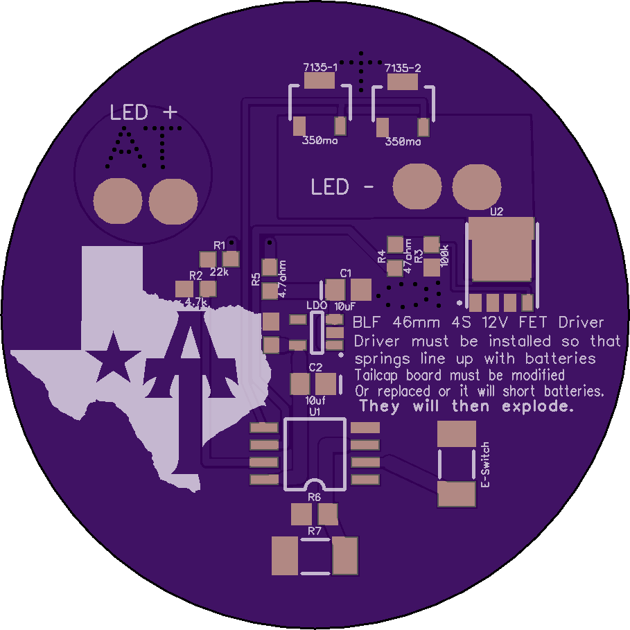
I am in the process of putting together a 4S driver for the SRK. I have a few projects that would need/use 2s/4s design so figure might as well go 4s since all the XHP’s can be run in both 6v or 12v mode.
I am laying out the Schematic, but having a hard time figuring out how the R5 and C2 components should be placed with the LDO.
The LDO needs a 2.2uf+ cap on the output wire anyways, could I simply replace C2 with a larger value and it do the duty of both the LDO and C2? If I add a second cap would it interfere with C2? I figure we would use a 10uf cap for the LDO, would the extra size negatively effect the role of C2?
I assume the R5 should remain as the first thing in the + side of the circuit.
Yea, Dr J can save an I/O pin by not using the voltage divider resistors and using the internal 1.1v source instead. Neat trick, and I/O pins are in very short supply... Could be then 4 pins can support PWM. yea, look'n over the datasheet, I see a 4th possible PWM channel.
TK uses Timer/Counter 0 for pins #5 and #6, and Timer/Counter 1 channel B for pin #3, and it looks like it can support another channel (A) for PWM.
This one is not a Texas Avenger series of driver simply because at these voltages the 7135 would not be good for anything but moon mode. But it has the same basic setup and I am putting it here anyways lol.
It is a classic SRK driver but setup for 4S 12V LED’s (or 4 LED’s in series). So this is what you want for an XHP35 / XHP50 conversion. It is pretty basic and sparse on the board, if anyone has something creative/funny to put on the silk screen feel free to let me know, got lots of room on the silk left.
Parts list is the same as above except the C2 change along with the LDO addition.
R1 : 220k
R2 : 47k
R3 : 100 k
R4 : 47 ohm
R5 : 4.7 ohm
R6 & R7 : Unused at this time, installed for future expansion options.
C1 : 10 uF
C2 : 10 uF
E-Switch : Momentary switch
LDO : SOT-23-5 form factor 5V LDO of choice, designed around MIC5235-5.0BM5
U1 : Attiny85 for Narsil, Attiny13A for Star momentary
U2 : LFPAK56 MOSFET (mosfet is the technical name, we call them FET around here)
That was another thing I was curious about, it would make these drivers in particular WAY easier to fit without having the external voltage devider but I assume without the external divider it would be limited to a 1s setup correct?
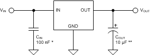
Just a amateur hack here, so please don’t take my statements to follow as fact. I would think the LDO will drastically change the situation. Check out the data sheet for your LDO. I’m fond of using the LM2936 and it recommends a 10uF Cap on the output pin. Check out this diagram from it’s data sheet:
The LM2936 data sheet has no limitation on the cap size, just a minimum. It also recommends a certain ESR. A .5 to 1 ohm resistor in series with a typical SMD Cap will accomplish that for the LM2936. Here you can see I have 20uF in caps a 4.7uF resistor (Way to high, was just trying it out) on DD driver for 4S cells. I used 47K (R1) and 4.7K ohm (R2) resistors on the voltage divider.
The LM2936 is way too big for our drivers (can handle 40v on input). Just giving a for example case for you to think about.
I figured it would effect things a fair amount but I am not sure how exactly. I guess one thing I didn’t take into account is the 5V output will change things a bit.
I figure a 10uf cap in the place of C2 will accomplish the cap needed for the LDO along with the C2. I have no facts to back that up though.
I obviously have plenty of room to add a resistor to the C2 cap if needed, I can add the pads easy enough and test later of course.
Any other suggestions? I just tossed this together real quick cause I was bored and didn’t want to spend a lot of time on it.
TA, keep the small resistor in front of the first capacitor. I would guess a 10 ohm or so would be ideal. You may even go higher since you have voltage to spare with a multi-S setup. The active regulator does change things, but I expect the ringing to be still there without this R.
You are OK with only the Cout of the LDO, depending on how close to the MCU it ends up. If you do have the space, a 0.1 to 1 uF C2 would be a nice to have.
You may need to bump up Cin to at least 2.2 uF, to prevent the LDO from seeing the FET turn-off spikes. This is where a resistor larger than 10 ohms can help.
It actually hit me this morning a FAR simpler and more efficient way of doing a 2s or 4s setup in a SRK. Kinda hard to explain but I will knock out a prototype setup and see what people think.
Thanks! been wanting to do this for a long time but just never had the time.
If TomE decides to make a Narsil for this type of driver that would truly complete my goal for these save for adding a 4th channel to the reset pin if that is even possible.
Yep, got all those sizes take care of along with a few variations of them as well. Also a 26mm that can be sanded down to ~23mm or so if needed.
I might measure the S70 and L6 drivers along with the DO1 and knock out some in those sizes as well just in case someone wants to swap those out as well, but those would need new firmware to be able to use the e-switch.
This leaves me with the second “issue” for a 4S SRK driver. I would really prefer NOT use an FET with a multi-cell setup. You loose so much efficiency doing that I just find it a waste, plus it is real hard to control current to what you want.
What I really want is a buck driver. I have done exactly zero research into buck drivers for flashlight use.
I know the RMM has a nice buck driver with good specs, a single coil would not hack it but using them either in parallel or multiples of them with each feeding a single LED would work.
Anyone have any good suggestions on components for a 2S & 4S (would prefer to use components that can do either with resistor swaps ect) driver?