I think it’s worth your time, Tom. As long as you don’t mind giving up your indicator LED.
Having a Medium/High/whatever you call it mode that is a consistent pwm-less level no matter the state of charge is really nice. It always annoyed me that my medium modes (the ones I use most) would “droop” so much as my battery wears down when using the FET.
Current control is very hard for sure, particularly at 4s voltages where you have enough overhead voltage to drive a single emitter at almost 200 watts if you let it flow freely!
That can be “controlled” though with PWM, this leads to the actual issue I was talking about when I said efficiency. The FET is indeed quite efficient, no worries there.
My issue is the LED efficiency when using PWM to adjust the current. You loose a LOT of output doing this along with a LOT more heat. For example Dale was able to get 2200 lumens from an XHP35 using what I assume was an FET driver and he said that was all it had.
Acebeam on the other hand are able to get 2600 lumens in the K70 in what I am sure is a setup that leaves a bit of wiggle room for more. I am positive they are using a Buck driver and this explains the extra output. They are also not using the latest XHP35 that cutter is selling I am sure as well and these numbers fall better in line with what I would expect from a properly driven XHP.
I know I am preaching to the choir about this but for those that do not understand, basically with a 4s setup an FET starts dropping the LED’s efficiency so you don’t get as many lumens per watt and it runs hotter as well. The change can be quite drastic as well.
I am not worried about regulated output, I just want the best output for a 6V or 12V LED possible.
Or is that a closed source driver? Those parts/specs x4 on a Q8 would make for a killer driver IMO. Might need to rework the MCPCB to allow connecting each LED individually but that might even be able to be added to the design before it is finalized.
Are there any buck converters that would allow for ~4A of driver current at 4s voltages and work work in a setup like this?
PD68 - Yea, that's definitely true. For single LED lights, the 2.1A-22.A is a nice #, where you figure 5A or so is 100% FET, so top medium mode of 42% is excellent, and like you say, it's a stable PWM-less medium mode. From what I see in the output level table in bistro-tripledown, almost all the modes are on the single 7135 or bank of 7135's, so for ramping, you get the same benefit, accept you don't know where the 100% of 7135 bank is, unfortunately. But still w/ramping, you get the benefit of not drooping output as the cell depletes for all levels accpet the brightest ones that use the FET.
I suppose though the ramping, if tweaked for cells at full charge, and as the cells deplete, the top levels won't change much - but still not a totally bad thing.
Scaling it for multiple parallel LED's is another thing - if max amps is 16A on the FET for example, then 2.1A is only 12% or so.
FOr Mtn MAX Buck, it's totally open - you can buy the parts and PCB separately.
That would be great if you got that done. Is it possible to get the 4th PWM channel on the reset pin? And/or move the voltage divider to the reset pin?
If so then the freed output could be used to control an indicator LED, which would be quite cool itself. Or it could control another channel of 7135’s. I am thinking 2x single 7135’s would give you moon, low and med modes, then all of them together could give you a nice high mode.
Course really you could make one of the single 7135’s non-PWM if needed as well, the key is if the reset pin can be used for anything. I doubt removing the voltage divider is possible with more then 1s setups.
Ahh, supposedly you can use the reset pin if you got the full development kit for the Atmel parts. Not a lot of money, can be bought at Mouser, think'n $50 or $60 or so? Now, I'm not sure what the limiting factor is - can you program it just once witha the USB dongle, or can't program it al all? Once the reset pin is used for I/O though, you can't program with our standard cheap dongles. Richard of course has the full dev kit, not sure if anyone else around has it - I've been debating buying it for a long time.
I ditto PD’s statements, that is the main reason I am building these drivers.
Far as the Q8, whats to say you are limited to 7-9x 7135’s in a Q8? I started playing around with a SRK driver based on this same setup but stopped since there was no firmware for it and I could not improve on the Q8 design by PD if not adding the 7135’s.
If the 7135’s were added in my early testing you could fit upwards of 16-20 without much hassle and still not be crowding the board, if you really wanted to maximize space I bet you could fit 24-26 but things would get cramped.
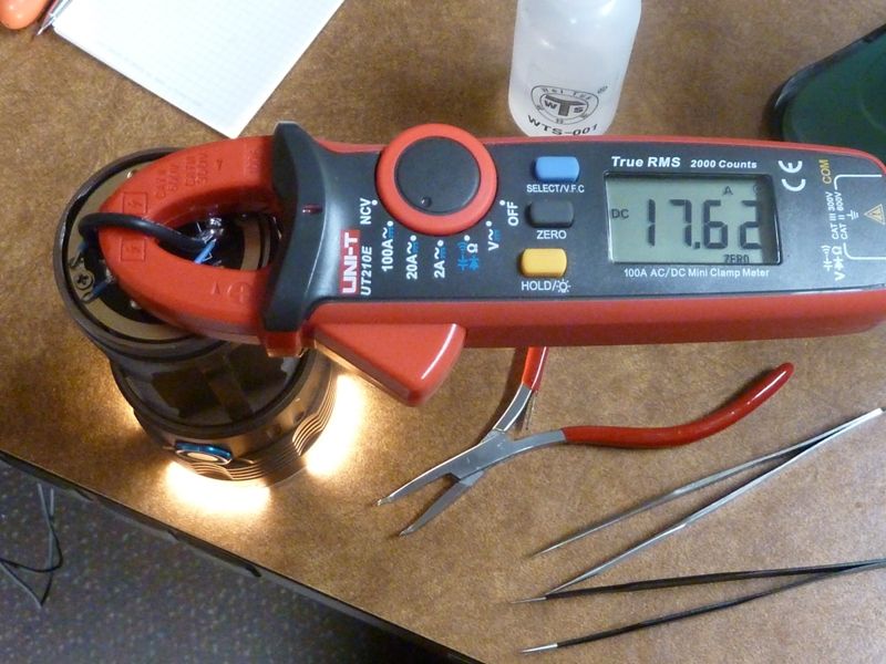
So that is up to around 7-8A of regulated current you could use in a Q8, which I honestly think is more then you need for a med mode but you also don’t have to install all the 7135’s from the factory. From my own testing I think around 5A is a good regulated number for a SRK light, the light itself can handle that amount of heat long term without getting too hot and it is still ~1800+ lumens (have not actually tested it at this level since getting my sphere working but good guess, might be more).
Plus turbo would seem way brighter if jumping from 5A to 16A. Can always add another mode between as well, say around 8-9A.
I will look into the MTN MAX buck parts and see what I find.
Interesting, not being able to flash at home with the cheap dongles is a bit of a bummer. oh well, I knew it was hopeful, as if it was easy I figured ya’ll would have done it by now.
Good idea for a pre-manufactured board though, the Q8 for example could use that if needed since I doubt anyone will need to reprogram that once Narsil is done.
ah… This has bugged me for a while as ive known these attinys can do four channels, but i have failed to see that implemented. this explains alot. Specifically for me is the lack of rgbw drivers.
I got a 5X SRK running Richar'ds 32x7135 board and added 18 more stacked, so it has 50 on a SRK, running an 85/Narsil. I waa disappointed with the amps I was getting, so I took an educated guess the traces for all those 7135's was killing it, and added a few 22 AWG teflon wire jumpers, and sure enough I gained 2A as a result.
I don’t like a lot of modes in general, all of my lights have either 3 or 4 modes only (except my S8, because it has red modes too) so they have big jumps between modes. On a single-emitter light I put my last regulated mode at either 1 or 1.5amps (rough). For a bigger light, I put it at 2.28amps. So my M6 goes from 2.28 to 14+amps in one jump. It’s so fun because the uninitiated think it’s already bright, then I click it again and… :cowboy_hat_face:
This is a problem true but since we know about it, we can also design the traces larger, plus there is a pretty big difference from 16-20 and 50 7135’s in a bank lol.
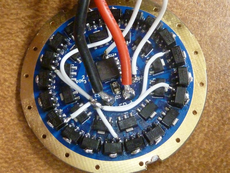
The design I was working on had one ring of 7135’s around the outside of the driver with the same current/signal rings like the other TA drivers.
This left plenty of room for all the other components on the inside.
I would agree, more then 3-4 modes is silly for most lights, in day to day use you end up just getting annoyed trying to figure out which mode is the “right” mode for the job.
Having a 3-4 modes and knowing that all but the top 1 or 2 are regulated is ideal for me, I don’t mind large steps in brightness as long as the steps are reaonably spread out (turbo being the exception, I find it kinda fun to have turbo 2 steps brighter then the rest), I either need more light, or I don’t.
EDIT: That said the ramping that TomE has been working on is a very unique alternative that I look forward to trying out. Not sure if I will use it long term as I tend to like a bit more control over things but I really like the idea for gift / loaner lights.
Been looking at the MTN MAX buck thread and I think that it will be simpler then I first thought to convert that into a SRK driver.
The only issue is the parasitic drain issues. Where does this drain come from? I assume it is from the Buck converter itself.
Tell me if this sounds reasonable:
Could this drain be eliminated by powering the MCU from the batteries directly as in the driver I posted above and not using the voltage regulator on the Buck converter.
Then adding a small FET to another pin of the MCU that would cut power/ground to the buck converter when the light was off / the MCU was in sleep mode?
This would seem to eliminate all of the parasitic drain when the light is off past what the MCU is using normally since everything else would have the power cut. The buck converter should not have any issues with delay on turn on as it is used in clicky lights.
Thoughts? If this is the case then it would seem that the standard MYN MAX setup with a bigger inductor would be a great match for a SRK setup.
It is also easily small enough to fit in a SRK / Q8 without a hassle. I am sure there are better options as well, just not got that far yet.
18A for a Quad XHP35 in the Q8 would be way more then enough for ~2500 lumens each and a total of ~10,000 lumens. It would also be a blistering 130+ watts I am guessing. The equivalent to a 16x XG-G2 SRK.
Yeah, I must build one of these now that I put it into words like that……
Yeah, that is a good idea since it would not be the same as these. Think I will leave the FET version here as it would work the same minus the second 7135 bank but the buck driver would be very different.
So to get this thread back on topic, I am about to order the TA drivers from OSHpark. I was curious what peoples opinions are on the 2oz copper / .8mm boards vs the normal 1oz?
I have only ordered the 1oz in the past but was trying to figure out if the thicker board has any benefits over the thinner one?
Think I will order one of them in 2oz just to see how it looks.
The 2oz option is actually half the thickness, but double the copper.
They are really really thin. Might be ok for a 17mm driver, but anything bigger I can see snapping in half under a lot of pressure or 26650 battery or something. I would just stick for 1oz for drivers, which is a shame because the 2oz gives better performance
I’ve used the 2oz option for some little 14-15mm boards and they’re pretty nice though. It seems whatever fab they come from has better QC or consistency than normal for Osh
The possible Q8 driver changes to a triple channel driver with 7135’s are welcome to remain here since it would fit in perfectly with the current lineup of drivers here.
I would personally love to see the Q8 driver add some 7135’s for a regulated med mode. In a production light the reset pin could be used for an indicator LED as well, which would be super cool!
Or since the Q8 driver would be 1S only, you could move the voltage divider to the internal voltage reference. It seems to work well. That would free up a pin as well and allow for both the bank of 7135’s and the indicator LED without having to use the reset pin.
I noticed the thickness difference, I could not figure out if it was a big deal or not but I can see your point, it would be thin enough to possibly crack under compression loads. Plus even just it bending a little could wear on the solder joints.
Back when we started the Q8, I didn't see the 7135 bank as a possibility, since then for me, there were too many unknowns, and didn't want to take the risk , plus the risk of having to spend more time in development/testing. Now however, it's a different story. But still, I have no triple board with to test. I could start the development in Narsil now for triple support, but I got nothing to test on. So, chicken & egg - do I go ahead and order some of your untested boards? I'm think'n - yes...
Also, not sure what you mean by the internal voltage reference working well? Uhhh, do you mean in Dr Jones boards? If so, there's no source code, no help there to cut down on development... It would have to be developed from scratch - all his work/efforts just means it's possible, that's all. Dunno if it would take me 4 hours or 80 hours to develop and test. I'm a full-time software consultant. I can't afford to take days off for my hobby, unfortunately at this point - I'm more than full-time bizy on my consulting gig, least through the end of the year, probably more.
 I'm think'n - yes...