Mind if I give it a shot in diptrace? I am sure it would be easier then by hand.
What is the MCPCB size going to be? And LED spacing?
Mind if I give it a shot in diptrace? I am sure it would be easier then by hand.
What is the MCPCB size going to be? And LED spacing?
Sure, have a go, thanks ![]()
The exact dimensions are not set in stone, it is a bit of a guess from other SRK dimensions and the latest drawings from Thorfire.
The external temp sensor (thermistor on Wikipedia) is the best, most reliable way to go, but of course requires yet another I/O pin, plus a lot of dev and testing. Calibration is the challenge - making it easy to do on a per unit basis is a challenge, unless there's a sensor out there that doesn't have a big variation from piece to piece, dunno.
An alternative is to ship the units with a default aggressive turbo-timeout. We will go beyond the safe zone of heat for what this host can take over time, plus the 4 cells will keep fairly high amps going for a while, though it's really equal to 4 individual single cell, single XPL lights, so should lose output/amps as it discharges. But of course going beyond the comfy zone is what this group buy is all about - as other BLF custom group buys have. Goal is to put a custom high output compact light into the hands of the many at a reasonable cost.
fyi... I'm a full-time consulting software developer, so my NY hourly rate is a little up there, but actually rates have dropped in the last 15 years with offshore and green card import pressures in the industry, and world wide access in general. Back in the 90's, 20 years ago, the rates were higher than they are now.
Ok, here is a very quick and dirty proof on concept for the mcpcb. I didn’t feel like making it look pretty if changes were going to be needed lol.
I swapped the LED pads 90 dergees from your drawing because I felt this gave a larger trace size to the ground plane.
The LED’s can be rotated back and a smaller trace to the ground plane used as well if people think that is better.
I only put a single pad for the LED + and - since that A: leaves room for the thermistor close to the wire hole and B: you can simple move the wires to the new location if you rotate the reflector, it would be super simple to repeat any cutouts at 45 degrees on the reflector.

I started working on a 12v / 4S version of the MCPCB but doubt people will really care since it would not effect most people and it would not be as clean as this setup. Although running the light in 4s mode would net noticeably higher amps/lumens but this was shot down early on.
In 4S mode you should be able to do the same as an A6 per LED, around ~5 - 5.5 amps and ~1500-1600 luemns per led. In parallel mode we seem to be getting around 4 - 4.25 amps per LED and around 1200-1300 lumens per led.
Not a major deal and not really an option since people said they want it setup in parallel. Having it work in both is doable but would not be as pretty / as uniform in the traces. Plus if someone really wants to get that crazy they could swap out for individual MCPCB’s I guess.
WAUW!
Thanks.
Neat how rotating the LEDs 90 degrees makes this elegant almost flower like patern!
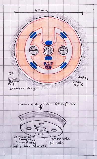
Please do not be insulted by my poor sketching, terrible colors (easier like this in my crude paint thingy)
The screws should be in pairs at an angle of 45 degrees right?
And that would mean the thermistors cannot be placed where they are now.
Correct me if I am wrong, and well I probably am ![]() but want to put it out there in case there is not all wrongness here in this sketch:
but want to put it out there in case there is not all wrongness here in this sketch:

Yep, you are correct, I honestly tossed the second set of screw holes in at the last min and forgot they need to be 45 degrees instead of 90. 90 looked so pretty I didn’t think about the fact it wasn’t correct. lol
I will get that fixed later.
Or should we swap the screw and wires? Have a single large screw in the middle with the wires coming out the holes on the side? Doesn’t change much for the holes but you could go a lot deeper without hitting a reflector in the center. So then question then is a single large screw stronger then 2 smaller ones?
Two screws protect from accidental rotation during assembly with the bezel and lens.
That s why we went with 2 screws.
Nice work sofar between the 2 of you. The screw holes where they are probably clear the reflector cups already. We want the wires in the middle because the cutout (2mm deep) on the underside of the reflector must not be too close to the reflector cups, sending them to the side may cause a bigger problem than the screws.
Good points, I will correct the screw holes.
In the 4 led version I pointed the led wire solder pads, and also the screw holes in between two leds, so that the reflector cut-out and screw holes would have as much ‘meat’ under it as possible, in this 2x4 led version that is still possible for the screw holes, but not anymore for the solder pads.
Edit: thinking of that, as the thick ledwires need the (rectangular) reflector cavity, the solder pads for the wires should rotate with it, in other words they have to be elongated in a circular way. The cavity in the reflector can not be widened to the side because that is where the screw holes are.
Please think with me how this should look like
The thermistor circuitry can easily be placed between two leds, so that the crowded middle of the board can be fiddled with more easily.
This is an option but was trying to keep the wires as short as possible but there may not be another option.
Here is an updated version with the correct holes and touched up here and there. I also extended the solder pads to allow them to line up with whatever cavity there is.
We could do 2 separate pads but it would be hard to fit 2 good sized pads in that space and keep them separate. I could do 2 overlapping circles though.

ha great! No need for me to hurt your eyes now wth this last revision!
Looks great!
Overlapping solderpads probably looks nice (almost like 8 holes there in the center) and from what I have been reading of the software you use are also probably easier to add then a free hand shape.
Yeah, 2 circles is a bit easier, I will swap them out real quick.
Naturally this will have to be redone by Thorfire so they can make sure everything lines up perfectly but this should hopefully be good enough to show them what we want.
Lets try this one on for size:

This looks like a smart, elegant and practical design!
thanks, I can go to bed with a big smile now!
I think this is going to work: XM-size and XP-size leds can be used on the same board without compromising the functionality. Nice!
It may need some fine-tuning (like tilting the therm.pads a bit to make the current path for led #4 a bit wider), make a bit wider clear-outs of the tracing around the holes and the edge, etc.
And perhaps looking at this design people come up with more clever ideas (add XHP70 pads as well :smiling_imp: )
Thanks for the very helpfull drawing and thinking sofar, Texas_Ace, let’s let this brew a little while ![]() …
…
Please add me to the list as well.
Thank you!
Ya’ll are too quick lol. I actually noticed the thermo issue just after posting the picture and was hoping to update it before anyone saw it. I had just tossed it out of the way and forgot to position it properly.
I updated the above picture with the pads angled properly.
The entire board will need to be redone by thorfire as I have no exact measurements to go off of plus this is something that would be best to have them do the final design work anyways since I have no idea what software they use and they need to work with the raw source files.