> hard to understand you guys.
Not your fault, words are hard to find to describe this stuff.
> step inside lower part of bezel.
“bezel” meaning the long tube that slides, right? That step sounds like what I see and how it works to stop the pill from sliding out the back end of that tube.
(I usually think bezel means the very frontmost part that screws on to hold the lens, but I understand what you mean there I think)
> PCB shelf
If the LED position is any closer than the stock distance to the lens at full extension, then you won’t get a focused image of the LED at full narrow zoom.
Most people like to see that.
(I don’t mind a defocused round spot with fuzzy edges myself, I get that when I stuff a disk of copper or aluminum onto the stock shelf, lifting a replacement LED up slightly)
(or for that matter when I use a LED that comes on a 1.5mm board — I think the stock thin aluminum board is at most 1mm thick, maybe less)
> too expensive
That’s what I was afraid might be the case, to get the cutout for the 16mm board, etc.
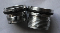
I think the single O-ring groove is necessary — without a groove for an O-ring or wire spring, the slider/focus will just flop around loosely if there’s a bit of a gap between battery tube and sliding tube. And I’d guess the dimensions on the clones are fairly loose so a pill needs that one O-ring to fill that gap.
I know people have replaced with thicker or thinner O-rings when the slider was too tight or too loose, or added a bit of lubrication to it.
For a flat top pill, I guess we can drill and tap holes for screws to hold the emitter in place — which would be better than the press-fit washer to hold it down.
Or solder a copper board LED to the pill, if there’s a way to keep it centered while soldering. I have got to learn that sometime (grin)
And centering the LED isn’t all that important for lens-type zoomies anyhow, as long as it’s fairly close to center, it looks fine.