Puzzling challenge for those in the know, mystery voltage when AC LED is present

Ok folks, this one is stumping me big time. I’ll try to lay it out as best I can and maybe someone will know what’s going on.

I have a Hunter ceiling fan in my son’s room. It has a light fixture that uses 2 candelabra base bulbs. Looks like they’re 25 watt but the existing bulbs don’t really clarify. Well, one has burned out and I wanted to put LED’s in it. So I went shopping for candelabra base LEDs that are the equivalent of 25 watt incandescent bulbs. Not a lot out there! I did find some Utilitech Pro bulbs styled like the ones I’m replacing at Lowe’s that are 4 watt 2700K. (supposedly a direct replacement at 200 lumens)

Now here’s where things start getting weird. I put one of the LEDs in the fixture opposite the incan bulb and it truly is a very close equal to that bulb. But when I tried to put the second bulb in it got weird fast! First thing, while the incan was burning by itself with an empty socket opposing it, the LED will not burn with the opposing socket empty. I was swapping em hot…yeah yeah shame on me. But now get this, turn the light off and the LED glows! Screw in the second LED and the glow is reduced even further and they both glow…power off! Neither bulb works when you turn the switch on. So they glow when off, nothing when on. And for more weirdness, replace one of the LEDs with the incan and there’s no glowing when off.

So, I got out the DMM and checked for voltage when the light is turned off. Things got weird all over again! With one LED in place (glowing although the switch is off) the empty socket reads 8V. With both sockets empty they each read 0.1V. What is going on here?

This fixture on the Hunter fan is controlled with pull chains or a remote that mounts at the wall switch but is mobile. This light has always been sort of odd in that any flicker of the electricity from a storm or whatever and the light comes on, possibly the fan. There are Hi.Med.Lo modes on the remote for the fan, but only an on/off for the light.

How can empty sockets read 0.1V OFF, then change to 8.0V when an LED is screwed into one socket?

I’d like both bulbs in there, but only if they’re trustworthy. One incan and one LED burn fine together and it’s hard to tell which is which with the diffuser on.

The LED in question is the Utilitech PRO from Lowe’s, part number 0199324, supposedly dimmable, G16.5 Indoor/Outdoor 25W equivalent and 200 lumens at 4 watt. 2700K color temperature. The bulb has text identification reading LG16512C20027K2 120V 4W 60Hz on one side and Utilitech PRO 206331 with SA inside a C on the other side.

I’d really appreciate any help y’all have to offer. Thanks!
If it is an older house then it is quite possible that they are switching the neutral. I see that frequently in older homes that still have knob and the wiring.

Another possibility is that you have a dimmer for the lighting side of the ceiling fan and it is giving you wonky voltage readings…

My opinion is that your neutral is being made through one of the incandescent lamps therefore you are seeing no voltage being dropped across hot and neutral because you have no path to neutral when the lamps are not installed.

If you aren’t handy with AC wiring then call an electrician. If you are, you should check the wiring above the ceiling fan as well as the ceiling fan wiring itself.

I have been known to check for voltage with the back lead wirenutted to a known grounded conductor somewhere else.

EDIT.
Additionally you might want to take the hunter remote fan control out of the picture and then see what things look like. I seem to remember someone else I have worked for had issues with this and could not install compact fluorescents because of the same result.

Thanks for the response themaindude but so far it isn’t tracing to any of that. The house was built by my dad in 72, all electric and wired by a company that dad used in all the houses he built…and he built a LOT, for over 35 years. There’s not a dimmer but there is an electronic remote control, wonder if that’s doing it? I’ll kill the remote and check it out. Not much way for me to mess up the installation, black to black and white to white, not any other choices.

Ah, I see your edit now…will do and will report back. Thanks again! :wink:

Ok, the remote was part of the problem but now I have 0.0V when the wall switch is off and only 7.7V when it’s on. The LEDs will flash then go out. The socket assembly says 125V with 75W max, so why am I losing 115.3V? I wired up a new fluorescent fixture on the other end of the house 2 days ago and the direct power leads (Romex) were reading 123V.

Makes me a bit scared to open up the light kit! lol

Did you disconnect the remote part from the wall. If so, there is also a reciever in the canopy. That needs to come out as well. Believe it or not. That remote is really wireless and just switches off and on at the wall. All the work is done at the reciever in the fan canopy.

Edit. 0.0 volts is a good reading with no power. The other voltage with power looks like a circuit that is dimmed.

Makes perfect sense, now that you said it! The wireless remote only activates the sensor within the fan housing, how could it be any different? I’ll get right on it…

Thanks again!

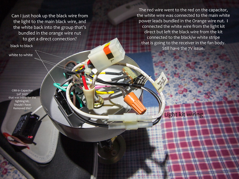
Apparently the receiver is hidden in the fan body, it’s not in the area where the wiring for the light kit is. So here’s a picture of the light kit assembly with switches and wiring. There are 2 CBB61 resistors in there, or there were, I took out the one that’s inline on the light kit. Why would there be an electric motor resistor in the light wiring?

Can I just hook the light module direct to black and white and be done with the remote unit? Or do I have to go inside the fan itself and remove the receiver? Or, (thinking as I proceed here) could the receiver be at the ceiling where the fan connects to the house wiring?

Sorry took so long to get back to you. The reciever is going to be in the canopy itself. That is where the wiring into the ceiling is. I think the cap you are seeing might be for the fan. I am on a cell phone. I have to get home to look at the lighting accessory kit picture yo have.

Edit. That cbb61 module that is inline with lighting harness. What is that red thing

Hey, no problem. I’m glad to get whatever help you can offer!

When you get to a computer you can view the pic in it’s original size and see everything in detail. There were 2 of the capacitors, one on the fan side and one on the lighting side. Never seen that before. I pulled the one on the lighting side and am considering a direct wiring connection for the light.

The capacitor that I removed is laying beside the light kit on top of the case for my cordless screwdriver. It (the case) has a red tag on it which happens to be right beside the red wire that was cut. The white wire on the capacitor was in the orange wire nut with the white wire from the light, the white wire from the reverse switch, and the white wire main lead for a total of 4 white wires in the orange wire nut. I removed the capacitor and connected the white light wire to the red wire from the quick-release plug that goes to the receiver. Which didn’t change much of anything on the DMM.

The Hunter fan is model 23928, but I cannot find any schematics or diagrams that are helpful. Nothing shows anything that might be that receiver, just the bare wires running through the vertical tube and connecting at the junction box.

Thank you for sticking to it on this, very very appreciated.

Really not sure why there is a cap in parallel with the neutral of the lamps. the fact that you are still seeing 7 volts tells me you definitely are dimming the circuit. big question, do you have dimming capabilities with the remote???.. the caps shouldnt have any affect except maybe dampen electrical noise created by the motor. I think you should plug the harness back in and see what your lamp brightness is and ramp it all the way up if possible.

That’s just it, there’s no dimming! Just an on/off button on the remote. Leave the pullchain on, then on/off at the remote. Unless it’s a ramping feature that works if you hold it down…it’s been in there for several years and we’ve never had it dim on us, even when my kiddo played with the remote.

I tried the wiring diagram I asked about on the picture…direct wiring the light to the black and white wires from the connector. NADA! Nothing. Zilch.

I’m ready to put it all back like it was and forget about LEDs. Stick a candle in there or something lol But seriously, I’m heading in there with my DMM again to check the connector and see what’s what. I even wised up a wee bit at some point in the day and put deck shoes on…had been standing on an aluminum stepladder barefoot messing with this dang light. :8)

I am sure it is ramping. Did you open up the top canopy. Somewhere on that fan is a box about 1.25 inch by 2.5 inch long. Has several leads coming off of it, as well as a white piece of wire that isn’t connected which is the antenna. You could look for this wire sticking out from the fan

Edit.
Check this out
http://www.google.com/url?sa=t&rct=j&q=&esrc=s&source=web&cd=1&ved=0CGMQFjAA&url=http%3A%2F%2Fwww.hunterfan.com%2FuploadedFiles%2FSupport%2FDownloads%2F41316.pdf&ei=g5psUcrnBqjM0wGMoIGYAw&usg=AFQjCNH7mSBQ_YM49xUfXtf_3ahLErvkzA&sig2=FExK7hZEBiWfqcBuQPY2kQ&bvm=bv.45175338,d.dmQ

Went into the connector with my DMM and got a 9V reading on what was supposed to be the light wiring, Red and White. So I took the canopy off, removed that remote receiver and wired the black and white leads directly to the black and white leads of the fan, with the black/white stripe from the light wired to the black wire.

Now the lights work just fine. But not the fan. It hums but doesn’t turn.

And while I’m being so careful, constantly being careful what I touched and keeping wire nuts on the wires I disassembled I got all the wiring done and went to put a light it the socket with the light kit hanging and the light came on! I’d done the wiring hot. Forgot to turn the switch off when I tested with the DMM. I HATE electricity! And came damn close to frying myself, yuck!

The fan/light receiver could have a ‘pass-through’ power supply. it requires a minimum of AC current to flow through the light circuit all the time in order to stay powered.
This is common on retrofit thermostats and wall switches. It makes the wiring easier (only two wires coming into it instead of three).
If that is the case, it will only work with incandescent (and most CFL) bulbs. They will not light up with a milliamp or two. LED bulbs will easily light up (or flash every few seconds) if supplied with a milliamp.
In a former job, we tried to design a wall switch that had this sort of power supply. We abandoned it because some LED and CFL bulbs would strobe every 5-10 seconds on as little as 0.25mA.

By taking the remote receiver out and direct wiring I have the lights working just fine. But the fan won’t work. The only circuitry is that capacitor, the reverse switch and the 4 position chain pull. The fan will hum, but won’t run.

For what it’s worth, the lights are nice and bright.

Do I need to put this 300V 5uf CBB61 capacitor back inline in the light’s wiring?

There’s a good chance the fan will not turn over without the capacitor.

There’s a different capacitor on the fan, does the one I took off the light kit interfere with the fan’s operation by it not being there?

What if I manually start the fan turning, should it then run? It doesn’t.

In agreement with Adam. The two caps you see are probably the start capacitors for each direction.

This is possible, but I’m not sure what’s going on there.

Did your remote have the three-speed buttons? Mine does and I think you need the remote in order to drive the fan.
It might go with one speed (full) without the remote.