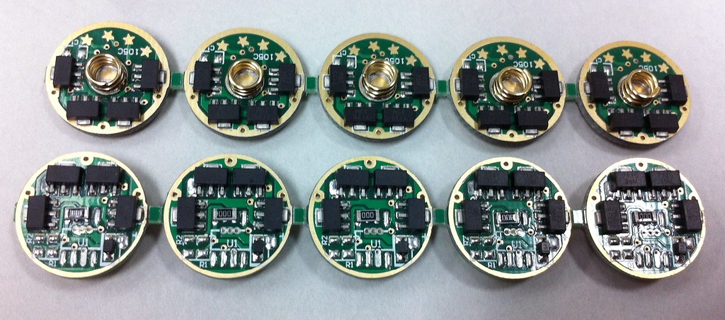
Have a few things I want confirmed before I solder this thing in. Generic 8*7135 105c with all components removed but the 7135s. Shunt in place of the diode, and between MCU pads for Vcc and PB1 (pins 6 & 8 ). LED+/- connected to the normal spots. Light comes out when I power it up.
Is this 'safe', sending full BAT+ direct to the 7135's Vdd? Or does it need the diode in place for, well, if I knew that I wouldn't need to ask, would I? :p
This is how I convert my Nanjg105C drivers to single mode. It’s the easiest way I have found. Simply run a small jumper from the positive output to the closest 7135 chip, instant single mode regulated driver fast and easy. The nice thing about doing it this way is it’s easily switched back to multi-mode by cutting the jumper wire with an x-acto knife if you change your mind later on.
E1320, your mod is simple, however the MCU is still attempting to turn off the 7135 chips by driving their Vcc to Ground. Since you have directly connected it to Vcc, the MCU port pin is sinking a lot of current while trying to generate any mode other than High.
This is a relatively small amount of current, maybe 20-30mA (I’m not familiar with ATTiny GPIO structure, could be more or less). I doubt it would blow up the MCU, but it is generally not a recommended thing to do.
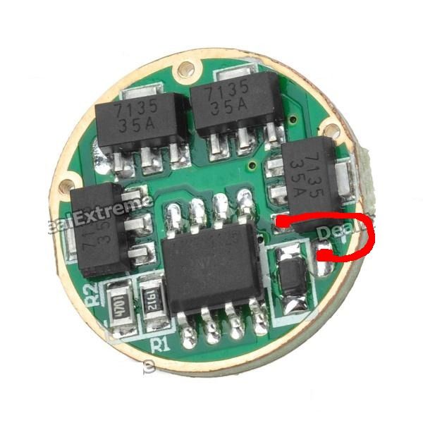
DrJones quote - "Take that driver (or look at a photo), locate the letters "L3AD4S" written on it, it's the pin directly above the letters "AD". (That's the third one counted from the little dent on the chip.)Cut it with some fine cutting pliers - or something else. (Damaging the neighbour pins won't be a problem.) "
I would believe that would work and still be able to solder it back, if modes were wanted.
As far as the reverse protection diode, I have removed them when using 3AA NiMHs to gain a couple tenths of voltage limit, before the driver goes DD. 3V down to 2.7V I believe, without the diode, but you do loose reverse protection.
There's a lot of "believe" in there, which means I may be totally wrong, but I am crossing my fingers that I said it right.
That quote referred to the KD V2. In that NANJG105C picture some posts above, it’s the 3rd pin in the top row of the MCU.
Since the diode is not in the main battery-LED path, you don’t gain anything from removing it (except the loss of reverse polarity protection).
So my recommendation is to connect the lower pin of the diode to the lower pin of the rightmost AMC7135 and cut the top-row 3rd pin of the MCU.
If you don’t cut it right at the case of the MCU, you could later reconnect it with a little solder blob and remove the added wire to revert your change, as Old-Lumens said.
Since nobody said "WHOA whoa whoa you can't put straight battery voltage to the 7135's Vdd, it needs the voltage drop from the original diode!" I'm going to assume it's fine that way, fully aware removing it defeats the polarity protection.
These were some boards that just didn't work right, weird random flickering (even on HI), sometimes wouldn't change mode, just weird stuff. I swapped a MCU from a dodgy board onto a known-good board and it worked correctly, and the 7135s on the dodgy boards worked correctly without the MCU (even in a bench test, being driven by the PWM out from a stock SRK's MCU). So I have no idea what the problem was, but I couldn't make 'em work right and probably wouldn't have been able to trust them even if I did. So they're destined to become single mode only.
*sigh*... I'm getting there, slowly... collecting parts to do it is easy, learning the strange alien language you coders use is where I hit a brick wall and have to put it aside for a few days until I work up the courage to dive in again.
It would be awesome if one of you smart fellers would write a simple, point-by-point 'install this, this, and this, in that order, then open this, load this file, press this button...' guide for complete idiots to at least be able to get comfortable doing the basics. Once that gets familiar, it's pretty easy to move on from there and start experimenting. But without a clue where to start it's hard. I think I'm pretty good at the hardware/troubleshooting side of things, but the software/coding stuff might as well be something from a parallel universe. S)
In your case O-L, you gained one extra thing. A slighty lower low battery point, which is what you wanted.
Removing the diode drop effectively lowers the low battery point a little bit, maybe 0.2V or so.
You know, I should really do that. Right now I couldn't because off the top of my head, can't remember it all. What I'm doing is keeping several mode configurations in one master source code, then uncommenting the one I want to build, commenting the previous one out. I should just post this updated source code so everyone can see how it's done. I'm bogged down with 3 Shockers right now (and then some) so can't get to it for a while...
Posting your source code that way would be a great help as well but I’m with Comfy on his suggestion. There is so much information scattered in the perfect modes thread that it’s really tough for non-coders like me to even know where to begin. If one of you guys who can do the reflashing of the drivers would take the time to write a concise step-by-step guide starting with what software to install on a pc, to what to open, where to enter what, where and when to click which button…etc. Basically a start to finish guide written as if you telling your grandmother in a single email exactly what to do to program a driver. If one of you would do that you’d be helping out so many of us it’d be silly. it’d also be GREATLY appreciated! 8)
Crap, I hear you... Wish I could get to this soon because I know I can do this... Actually the flashlightwiki is really close, here: http://flashlightwiki.com/AVR_Drivers, but it's a little dated, too technical in some areas, and is not a clear, concise, step by step approach for what you would do today. It looks like the wiki is still well supported and user contributed as noted here: https://budgetlightforum.com/t/-/17554, so that may be the perfect place to host this, or simply update what they have, or have an alternate, simpler write-up.
Maybe I can start on it this weekend - I may be contacting brted on it...
I think that flashlight wiki is pretty good. It helped me tremendously. I wish I would have thought to document what I had to do beyond it to get up and running. It wasn’t much. Here is what I can remember:
Connecting to VCC is manditory, at least in my case.
I think figuring out which pins were 1, etc on the usbasp was a challenge.
The software area may have been a little vague. It mentions a program that Tido uses. Not sure if beginners need extra info like that.
 .
.