my multimeter fails me. Been with me for two and a half decades now, but when I now try to measure current I often get visibly wrong readings (LED is dimmer while measuring) or no reading at all (only one short flicker), which seems to be a problem with PWM and buck or boost conversion.
I read much on lygte-info.com (can’t thank him enough, especially for the battery tests and the rewrapping tutorial) and have to admit that even the cheapest Fluke multimeter does cost a lot more than I’m willing to spare. What I’m looking for is - of course - the best budget DMM that meets the demands.
Which is:
Being able to read voltage and current, at tailcap and LED, even with PWM and buck or boost drivers.
I don’t need maximum precision, just reasonable values, let alone readings at all. So which specifications does my new DMM need? For all I’ve read RMS seems to be the feature to have. Is that all? Will any DMM with RMS be suitable or is anything else required, like perhaps frequency measuring? Is there a difference between RMS and True-RMS or is this just marketing talk?
As far as I have seen the Uni-T UT61E seems to be the budget DMM with RMS, and it happens to be available and even happens to be reviewed by HKJ.
He wrote “The meter is a true rms meter, this means that it can measure correctly on most AC voltages/currents, not only clean sinus waveforms.” As on most is not on all: Does that imply it is suited for flashlight-drivers even with a high PWM or buck/boost, or where are the limitations?
The pricetag seems reasonable but upper limit for me, so I am very thankful if you could point my head in the right direction.
You do probably not need RMS, it might even give wrong readings. This does not mean that a RMS meter would be a problem, RMS is usual not active in DC ranges.
For current measurements you need lower voltage drop, there is a couple of ways to get that:
For some meters, you will gain a lot with home made current probes, because the supplied might be useless for current.
Another way is to use a resistor and measure volt across the resistor, 0.01 ohm is fine for 0.5A to 10A, especially if you have a 0.2 volt range on your dmm.
Hello HKJ,
thank you very much for your kind answer.
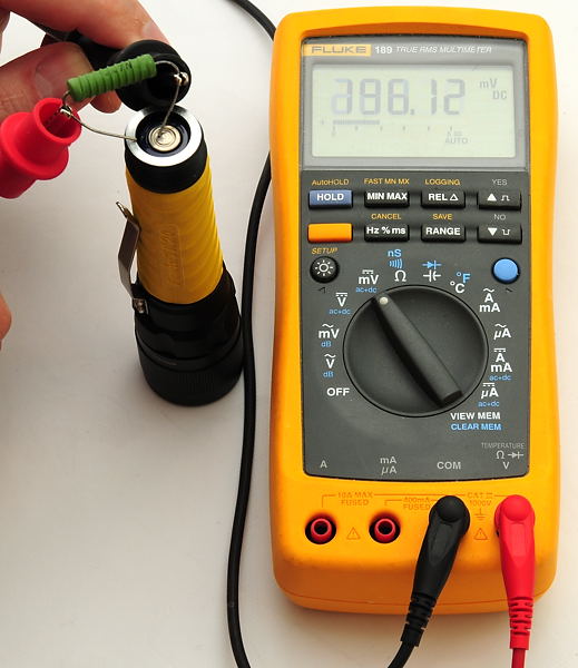
So if the shunt matters most, I can and will use this setup: (picture by HKJ…) 0:)
Calculating the voltage drop, 0,01 ohm for higher current and 0,1 ohm for lower current seem to fit.
But that still leaves me with the basic question: What kind of DMM do I need to measure the voltage drop with half-decent precision, even when different PWM frequencies are involved (KD, Nanjg, Qlite) or a buck/boost driver.
Or, referring to your pictured setup: Would the “Best DT9205A”, that failed because of PWM at tailcap-measuring, have shown a close-to-Fluke result while measuring via the shunt?
First: Fluke is not the holy grail or something like that. Most of their meters are nice, but that doesn’t make all measurement problems go away. You still have to pick up the right tool for the task.
I cannot find any manual for a “Best DT9205A”, so I cannot say what properties the meter has and what mehtod it used. (If that is documented in the manual, it may as well not.)
Some meters have the capability to measure rectangular signals within a low frequency range (a few kHz), but you would have to consult the manual to find out.
If your Voltage range is still working and you want to use an external shunt anyway, you could add an low pass filter first and see if it shows something reasonable. (something like 10kOhm and 1µF for fist try)
Or get a cheap scope. People are thowing really nice analog oscilloscopes away these days. oO
To show the concept:
Here you see a rectangular current of ~527mA peak and 50% duty cycle. So, average should be ~263mA.
I added an low pass filter (with very low cutoff freq for the 100Hz PWM, I hope dimming freq will be not lower than that ), and as you can see, the filter integrates the rect. nicely. The DC with a litte ripple is ~26mV avg and even with older DMMs the displayed value should be a little bit closer to reality.
thanks a lot, although I admit I was apparently just searching for that one affordable DMM that can cope with a pulsed (rectangular) signal all by itself … you know … the easy way …
It seems you can’t tell before. I looked through the manuals of Uni-T UT61E and Fluke 115, did not find anything helpful in both.
But I like where this is going, might me a true budget solution, as I can use my DMM for another 25 years
One or the other thing you and HKJ said are slightly above my head, but that’s ok for me, google’s my friend. I know what a lowpass is, built and used it in audio, but I hardly understand what it does to the PWM signal, read it makes an analog signal out of the digital one. Well, I’ll just try… R-C is easy, yet waiting for the shunts.
Could you give me one last hint, please: You wrote 10k and 1µ (= cutoff 15 Hz?), your picture shows 10k and 10µ (= cutoff 1.5 Hz?). Does it matter or make a difference?
Is the cutoff frequency in any way related to the PWM frequency, which in recent drivers seems to be between 500 Hz and 18 kHz?
Yes, it does make a difference and is related to the PWM frequency.
I used 10µ in the simulation because I wanted to show it with a 100Hz PWM.
For 1KHz and above, you could use 1µ.
Well, it’s a question of perspective. A rectangular signal like PWM is really just an addition of many sine waves of different frequencies. If you remove some of those signal components with a filter, you get a different signal shape.
It’s not much different to your audio application.
Cutoff doesn’t mean anything behind that point is gone, it’s just 3dB dampened at his point. This 1st order filter has a slope of 20dB/decade. So for example a signal component with 10 times the frequency of the cutoff frequency is overall dampened 23dB in magnitude (which means it’s only 14.125 times smaller).
Let`s say you have a 500Hz PWM and get above your shunt resistor a 250mV rectangular signal. Let’s also say you want not more than 2.5mV ripple at your multimeter. So you have do damp the PWM freq. by the factor 100 which is 40dB. We know we got 20dB/decade damping, so we need the cutoff frequency to be 2 decades = factor 100 lower than the PWM-Frequency, which would be 5Hz.
5Hz cutoff with the 10k resistor would be a 3.2µF cap. Let’s see:
Seems to be right.
[QUOTE=HKJ]
Fluke might not be the optimal DMM for hobby purpose, but for professional use Fluke are really good.
[/QUOTE=HKJ]
The make really nice meters, and so do quite some competitors in the same price range.
But as you can read above, that was not the point of my “holy grail” statement. A Fluke meter also must be used correctly to get correct results. Using a Fluke does not make the measurement correct by default, and their results are not reference by any means. That doesn’t belittle their build quality or reliability, it’s just the reality.
Usual a DMM's can handle 100 Hz pwm with reasonable precision without doing any filtering. But you will have harmonics and at higher pwm frequencies the input of the dmm will have problems handling them.
My statement was not really about precision or reliability (although this also count) of Fluke or other DMM's, more about the fact that Fluke tries to make purpose build meters (especially for electrician usage), they have the needed functions and is easy to use and that improves the possibility that they are used correctly. This makes them very good for professional use.
Some other brands try to add as many functions as possible to the DMM's, this is often a disadvantage for professional use.
I hope so.
In the kHz range, things might be different tho. Especially with cheap DMMs with crappy input circuitry and insufficient ADCs and/or signal processing.
Their user manuals often don’t tell anything about freq. response or non-sinusodial waveforms.
Just wanted to spare the OP from the disappointmend of spending money on a cheap DMM and having it show crap again, thus the idea of some cheap input filtering.
I misunderstood you there, thank you for the clarification!