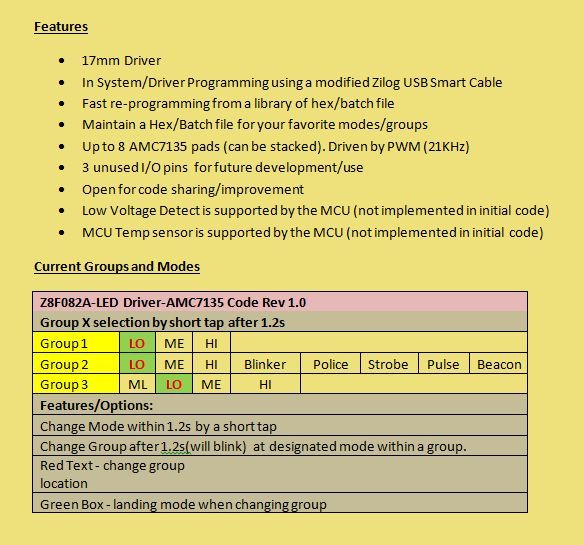
o 3 Groups:
Group1: Low(L)-Medium(M)-High(H-Moonlight(ML)
Group2: L - Strobe
Group3: L - Ramp Up and Down
o Change mode within 2 secs
o Change Group on Low mode after 3 secs indicated by a blink.
o Memorize mode if no change in mode and group
o Low Voltage indicator/switch to low mode
o Easily re-programmable
o 3 MCU pins available for other features
Yeah, It’s my job. Pays to be fast when you’re a salary employee who doesn’t get overtime
No problem. That’s an easy change.
Really wish you would have mentioned that or included a few of them in your schematic. I would have used smaller parts and done the layout very much differently… I’ll see what I can do without spending a ton of time on it…
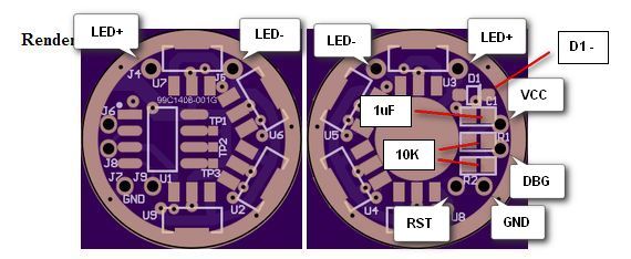
How about looking at the artwork which shows it’s already connected with a big plane of copper?
Best of luck with the Zilog. I have to admit, the only reason I knocked out the layout on this is because I was so shocked to see someone using Zilog. I forgot they existed! I'm turning off the work engine for the night, but I'll see what I can do with this in a few minutes tomorrow.
Well, it was kind of an obvious (to me), from that first schematics that 1 x AMC setup is just for testing purposes, otherwise not much use of a 350mA driver, right!
Easiest way would be to add another pcb with only AMC stacked like Mattaus 16xAMC slave board and one could add suitable number of regulators depending on drivers use...
I’m an engineer. Nothing is obvious and I don’t make assumptions about what the original designer intended. He posted a schematic of a 1X AMC7135 board and asked for someone to do the PCB/Layout. I made a PCB/Layout from his posted schematic. Should I have changed the processor to an ATTINY or PIC since it’s obvious no-one in their right mind would use Zilog?
actually, now I see that OP did mention in his post this:
so, my bad, I just assumed that schematics contains only one AMC just for simplification and easier understanding and the idea is to get XML driver (2,8A+) but it seams that OP wanted 1 or 2 AMC driver and then later on, when you already offered a pcb layout he changed his mind…
Once again, Look it over… Because…
A) I spent very little time on it…
B) It was not easy to cram in everything that’s on a NANJG, plus two resistors, plus six thru-hole wire holes.
Thanks PPtk! It’s really very close to what I have in my mind.
I have not done a PCB layout/trace review but will do my best provide feedback on any issue.
Would be great if other BLF’ers try to evaluate this. It’s really easy to modify the code. But
one need to get a Zilog USB Smartcable for programming. The Development/Proggramming Software is free.
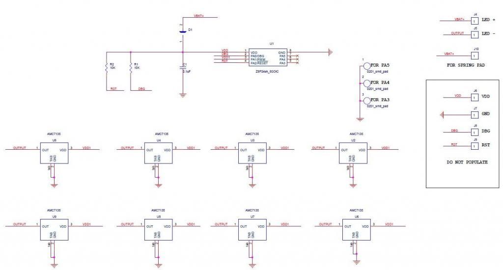
You’re welcome. Here’s a quick update with something I thought of. By connecting the AMC7135 chain to both Pin 3 and Pin 5 of the microcontroller, the board can now be used for the Zilog Z8F042A-SO8 or the PIC12F1840 (likely many other PICs in the SO8 Package). ATTINY Won’t fit because Power/Ground are in totally wrong places.
If using the Zilog, set PIN 5 to Input. It’s not usable that way, but it won’t hurt anything.
If using the PIC, set PIN 3 to Input. It’s not usable that way, but it won’t hurt anything.
Beautiful! Zilog for the strange guy and PIC for the normal people.
Programming pins are broken out for both Zilog (VCC/VSS/RESET/DBG) and PIC (VCC/VSS/MCLR/PGD/PGC)
That’s what I meant - Power/Ground are in totally wrong places on this PCB. I fully agree with you. The only nice thing about where PIC/Zilog put it is that it gives a nice place to stick a decoupling cap…