Review: LXP SS Bezel Flashlight (Int'l Outdoor Store)

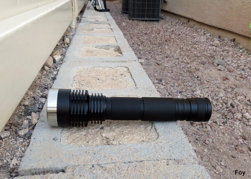
LXP SS Bezel: Creatively Named, Awesome Flashlight

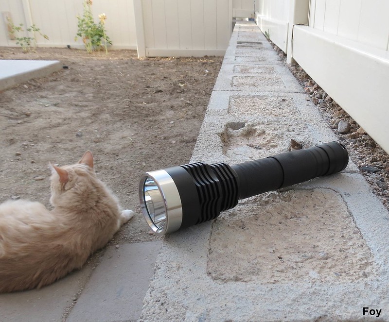
I'll go ahead and say it; I really like buying flashlights from Int'l Outdoor Store. There is a large selection of unique and (mostly) original designs and the recreations are usually better than the "inspiration version." The LXP doesn't seem to be a copy of anything. It reached out to me because of its old school D-size grip, hefty metal around the pill area with plenty of fancy cooling fins and convertible one or two battery versatility. I also like the extra run-time and power of 26650 cells. For the bling averse among us, IO does offer nearly the same torch with a single group of six cooling fins and black crenulated bezel. For an extra $9.95 that particular unit can be optioned with this shiny bezel, bringing its total to $56.93, making it about $3 more than the light shown here with its more ostentatious cooling fin design. It became an easy choice for Foy.

Foyapproved

Bottom line: The obvious comparison in the Foycollection is my similarly sized, E1320 modified Shadow JM05 that pulls around 3.10 amps at the tail. Interestingly, at 2.30 amps (2.80 amps advertised) the LXP reads slightly higher on (the admittedly flawed relative brightness measurement) Foyometer. It does nevertheless, have a tad more output and is one of the prettier cool white tints I've seen. $54 is quite an investment however but you do get a substantial hunk of a flashlight with more than just one battery option. A thick, screw-in brass pill surrounded with lots of heavy cooling, dual red O-rings on all tubes and a collector-worthy stainless steel bezel make this LXP a perfect hand-held lighting tool or shelf queen.
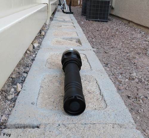
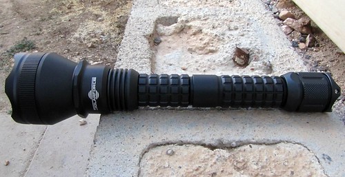
Ted and LXP

What I like:

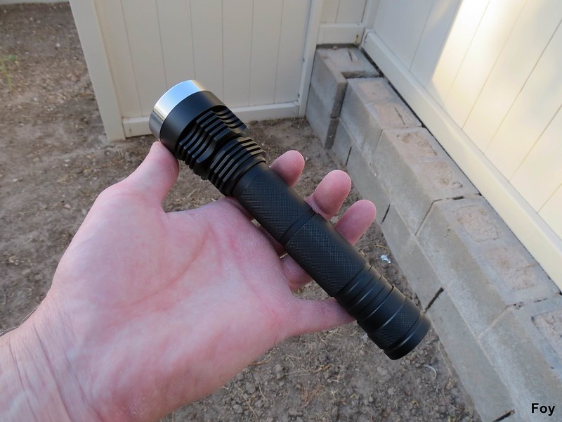
- big hand friendly fat

- large, screw-in brass pill

- beam profile/tint

- output

- battery options

- hidden blinky modes

- dual O-rings (and red too)

- stainless steel bezel

- reflector cooling fins and seating solution

- unique side-tie lanyard holes

- included kit

What I do not like:

- non-matching, larger diameter extension tube

- smooth knurling

- DIY lanyard making project?

- advertised 2.80 amps, 2.30 amps measured

- wish it was the improved XM-L2

LXP Stainless Steel Bezel 1/2 x 26650 XM-L/U2 (1B) Flashlight

$54.00 Int'l Outdoor Store http://intl-outdoor.com/lxp-ss-bezel-1226650-xml-u2-flashlight-p-519.html

ordered: 4-22-13

received: 5-20-13

Cree XM-L/U2/1B emitter

brass screw-in pill

fully regulated

aluminum SMO reflector

designed for one or two 26650 lithium-ion rechargeable batteries

ascending 3-mode or 5-mode user interface with mode memory:

low (100mA) medium (700mA) and high (2.80 amps) or

low, medium, high, strobe and SOS (hidden modes accessed by activating on low for 3 seconds, light flashes once, quickly turn off and back on)

aluminum alloy construction

"hard anodize" finish

square cut threads

dual O-rings

tail standing, reverse-clicky tail cap switch with GITD 16mm boot

GITD bezel O-ring

waterproof rated: IPX-7 (immersion up to 1-meter)

selected manufacturer specifications:

900 lumens

current controlled circuit (no PWM)

reverse polarity protection

low voltage protection: single cell/3-volts; double cell/5.8 volts

148mm (single cell length) 211mm (double cell length)

31mm (body)

49.2mm (head)

207g (single)

244g (double)

what you get for $54.00

- LXP flashlight

- extension tube

- extra O-rings (4, red)

- assemble-it-yourself lanyard kit

- extra DIY switch

tail cap draw: with 2 x unprotected King Kong 26650 INR

low: .06 amp (.12 to emitter)

medium: .42 (.84)

high: 1.15 (2.30)

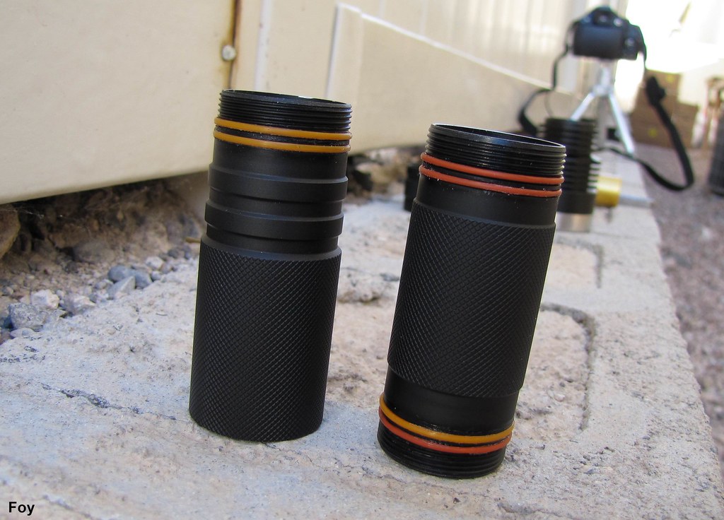
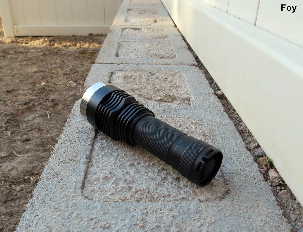
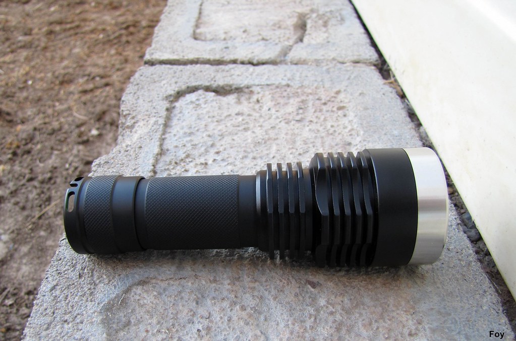
Finish is a strong buff black that I'll assume is type II. Gentle rolling on the Foywall had no effect and my only coating complaint (small though it is) would be a slight finish inconsistency on the knurling portion of the extension tube. Mine has a barely visible lengthwise line suggesting sustained rubbing of some kind. I only mention it as a matter of record because it is hardly noticeable.

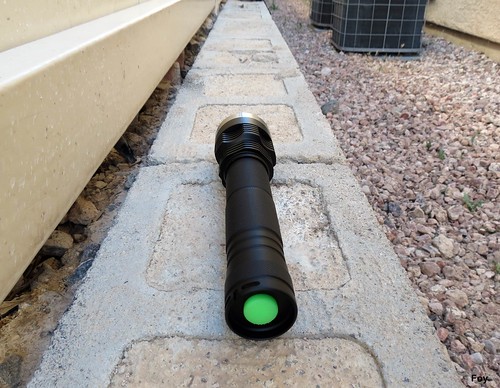
Like its XinTD/C8 order companion, the LXP shipped with a GITD boot that Foy swapped for black.

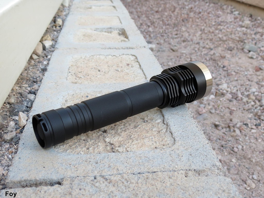
A very attractive torch, well proportioned and high-end in appearance. I like the D-cell feel in my large hand and I listed the knurling as a minus only because I prefer it a bit more aggressive.

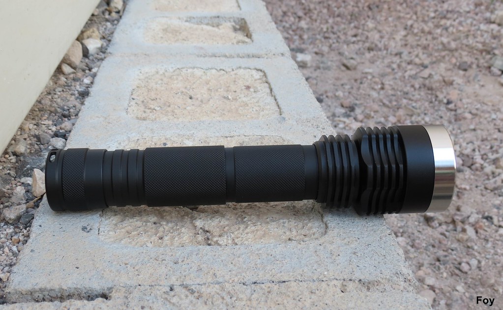
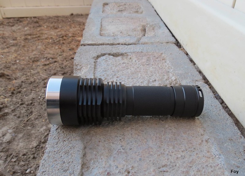
My only actual gripe has to do with the mis-matched size of the extension tube. The flashlight body and/or knurling should be same-diameter thicker or the extension tube made flush with some sort of transitional arrangement . . .

. . . such as one of these. Certainly not even close to being a deal killer but it would have given the light a professional polish in execution.

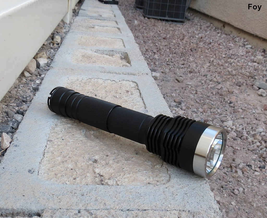
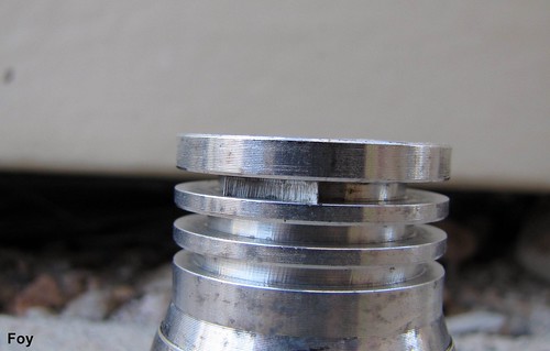
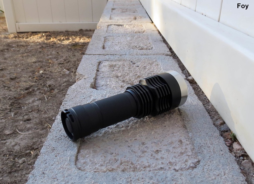
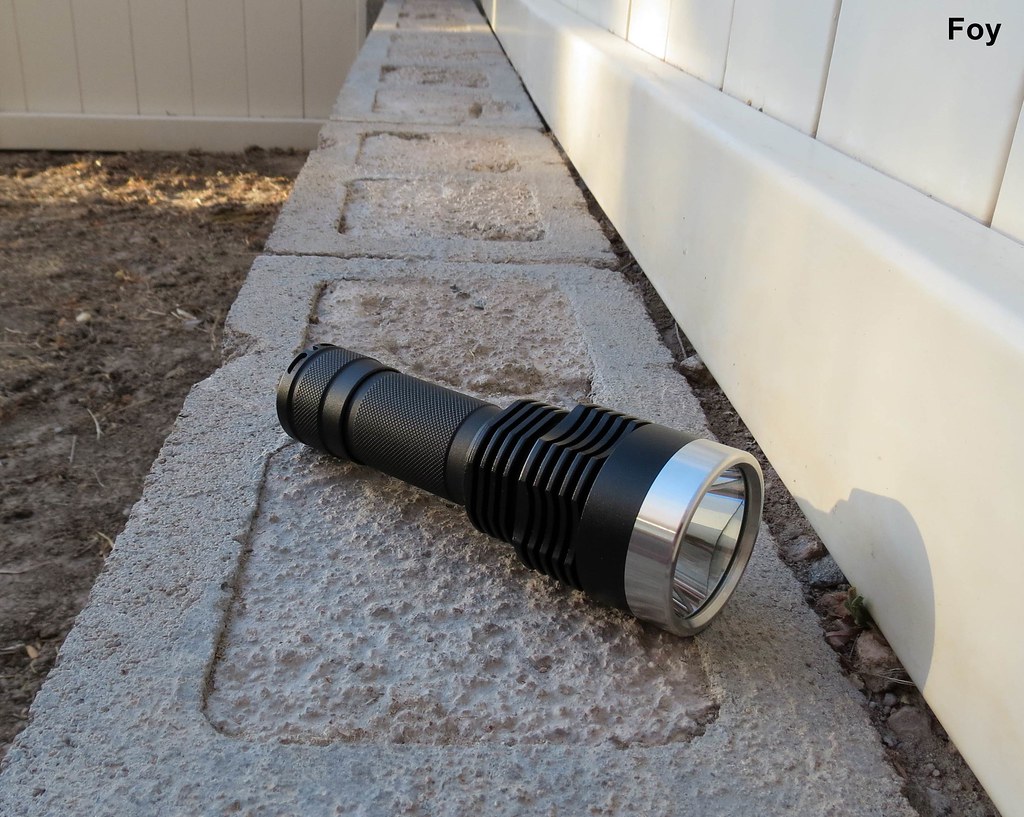
The LXP has 5-upper and 4-lower deep-cut cooling fins; the upper being scalloped on five sides and the lower cut smooth directly below by the same number. Thick area above the fins and below the bezel is just shy of 15mm of smooth aluminum and the heavy brass pill inside threads to exactly the middle of each set of fins. Thermal pathways conducting heat away from the emitter would seem to be excellent.

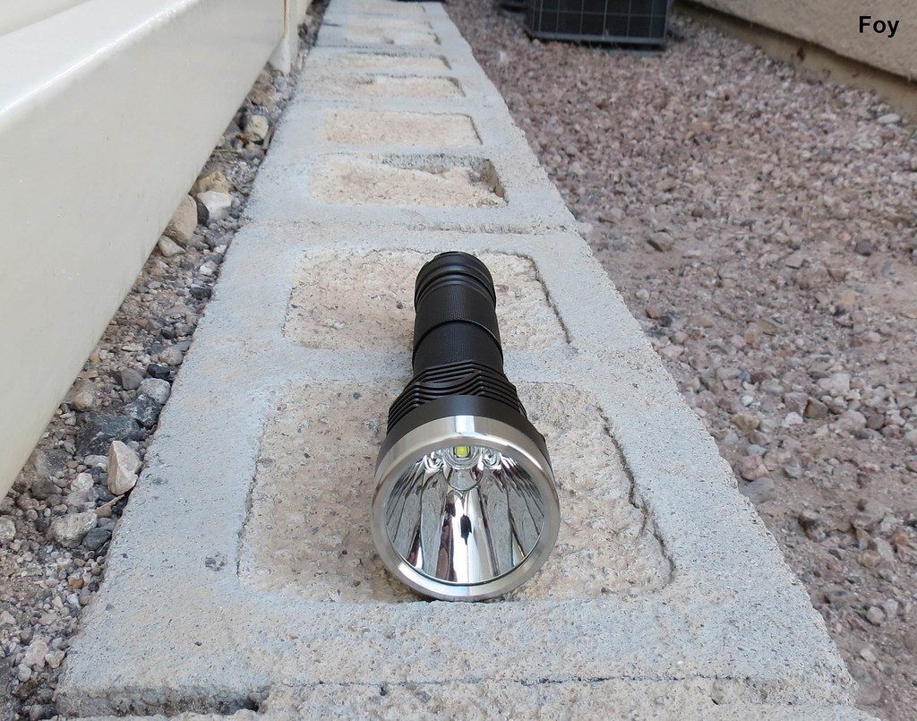
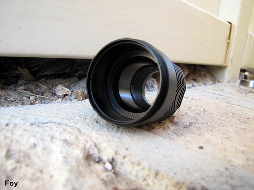
Aluminum SMO reflector is gorgeous and emitter is perfectly centered.

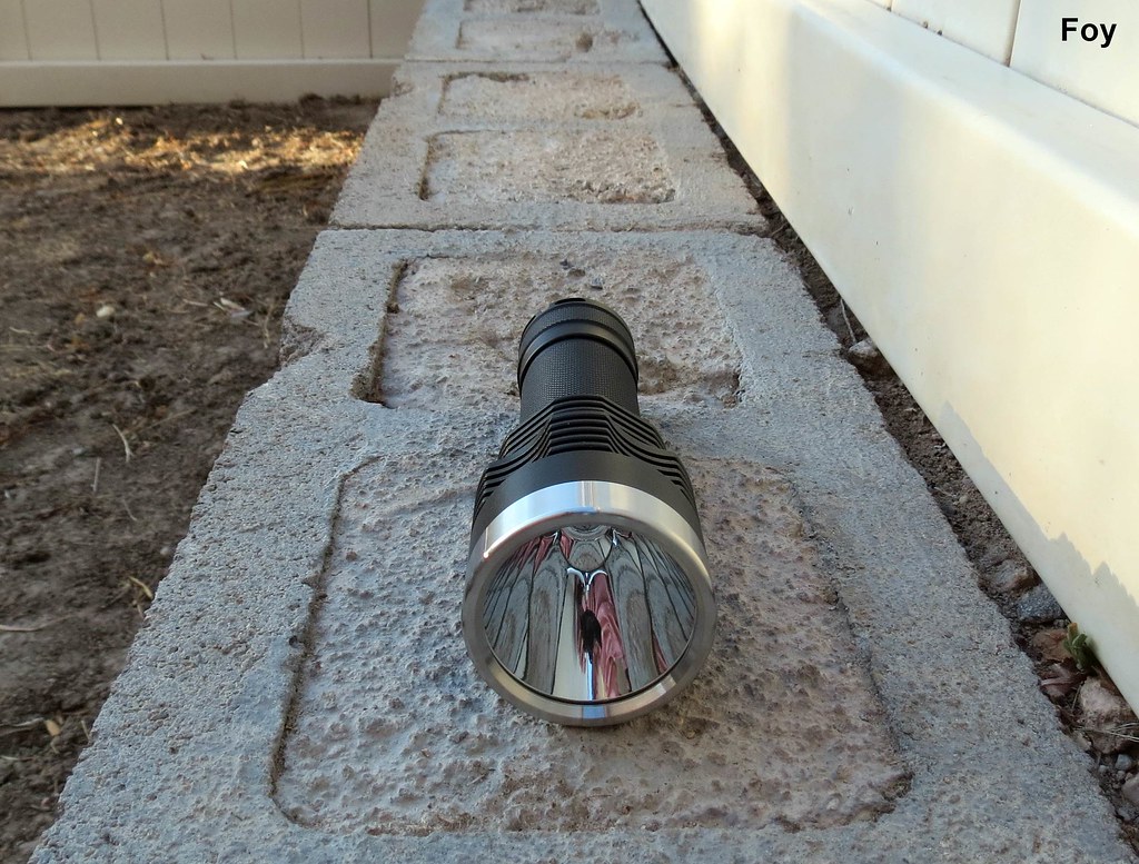
I didn't notice the improperly seated bezel O-ring until I uploaded this picture. The GITD O-ring fits easily in the inside groove of the bezel and when threaded on slowly, seats perfectly.

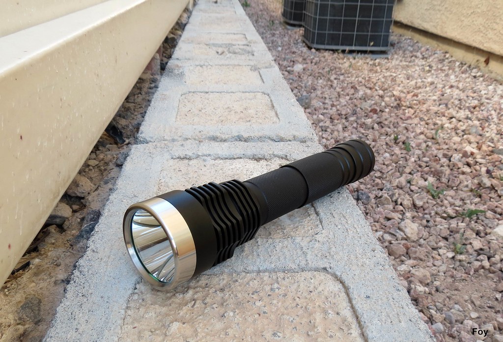
You can see how deep the fins are cut in this shot. Light is rated IPX-7 which is down to 1-meter. In the shower with Foy and there was no ingress.

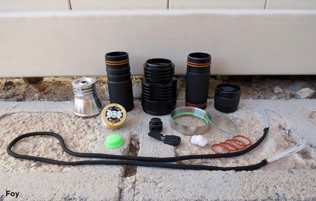
The LXP is a quality package all the way through but one must question the granddaughter-craft-projectesque inclusion of a DIY lanyard kit. Amusing rather than annoying and the different orange O-rings seen installed here are simply because Foy prefers a bit more resistance when threading on components.

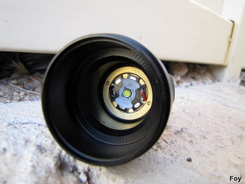
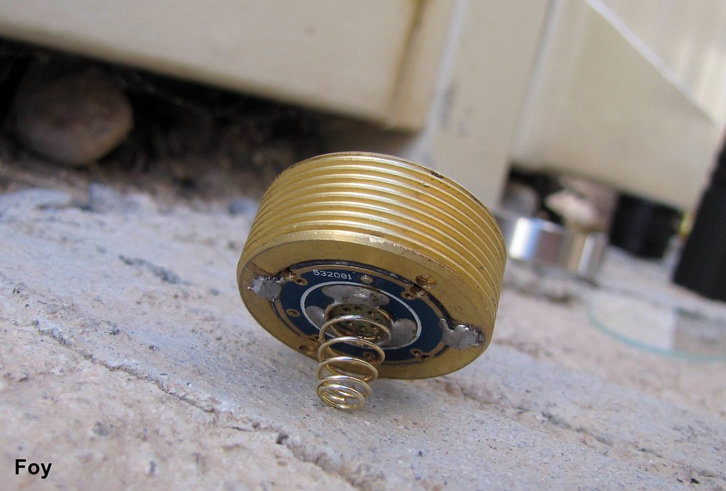
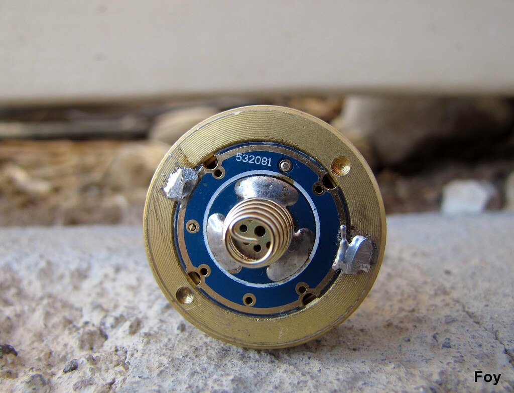
Brass pill threads in all the way through with no stop. To achieve proper depth, install reflector, lens and O-ring (inside bezel) and tighten bezel completely. Then, thread pill until snug against wide outer ring of reflector. Rather than just the center opening of the reflector coming into contact around the emitter, you can appreciate the thoughtful design of having the reflector also seat around its outer edge against the top locking ring of the pill . . .

. . . and the inclusion of cooling fins around the base of the reflector. And, apparently, leftover material from its time on the lathe. (shaving lifted right out with tweezers)

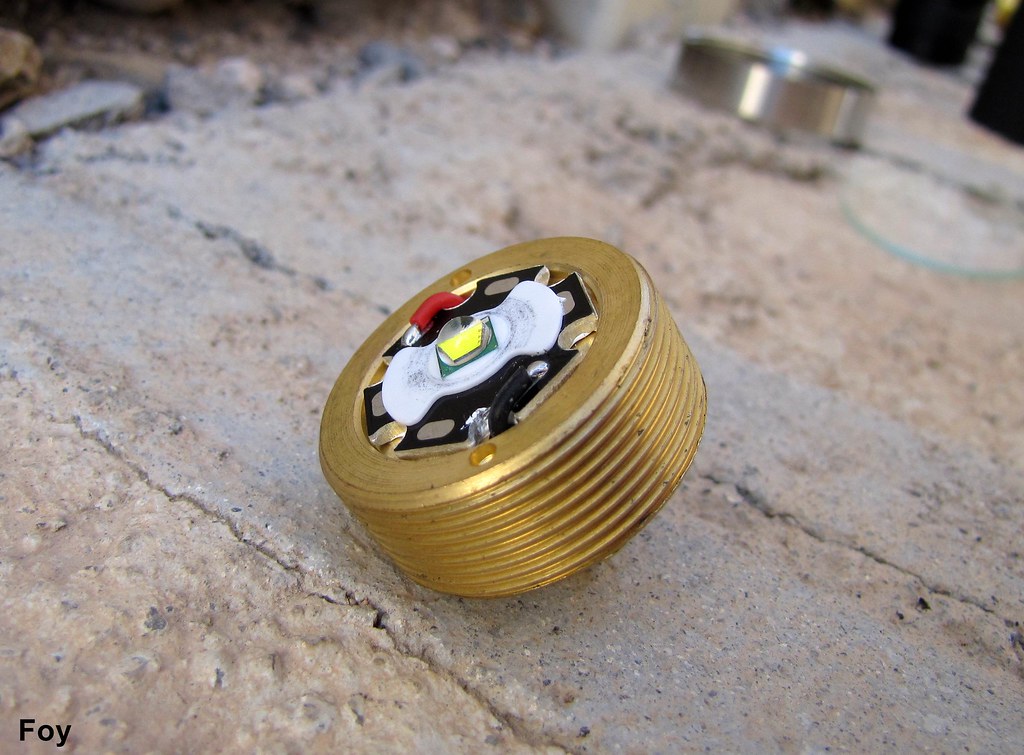
This is the kind of pill a flashaholic likes to see . . .

Lots of threads and they are cut thick and square . . .

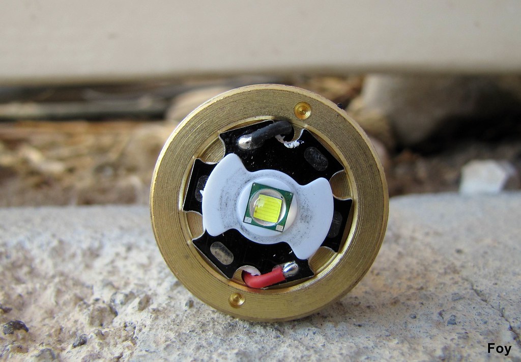
XM-L/U2/1B cool white.

I love how the spring solder is nearly perfectly shaped. Just another nice feeling of quality.

Double O-rings and anodized threads that feel absolutely fantastic.

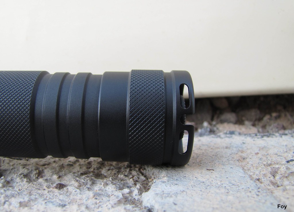
I also like the cut-out between the lanyard holes.

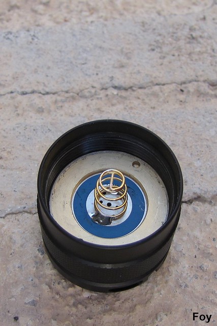
Recessed tail cap switch with 16mm boot. Nothing unusual inside about the switch.

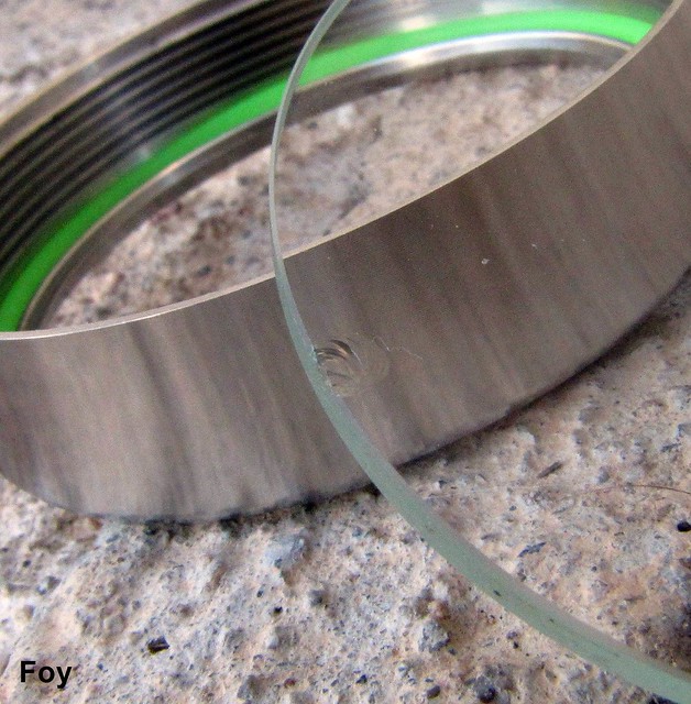
Inconsequential but for the record, small chip in the lens.

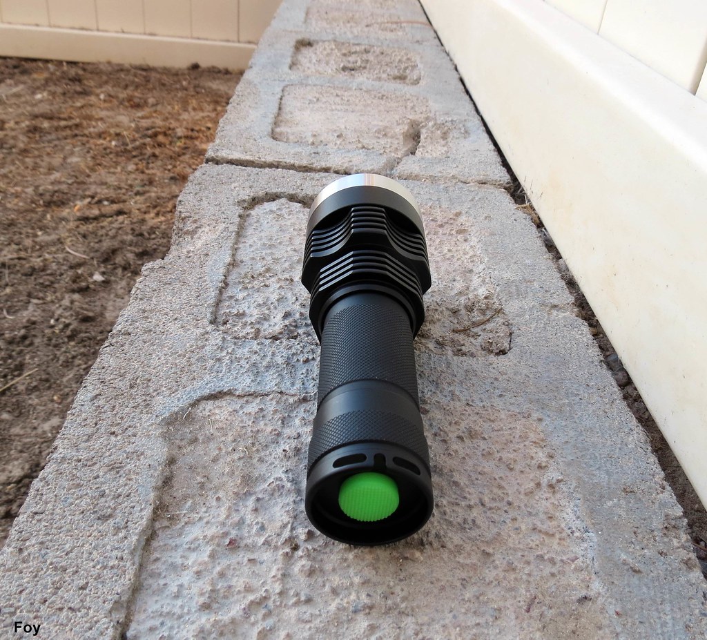
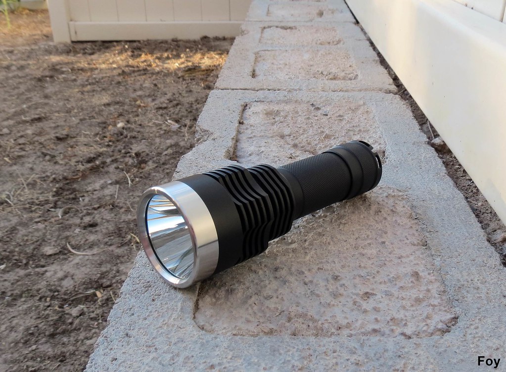
The LXP also makes a great looking single cell light . . .

All beam shots were taken with a 1/4 second shutter speed @f2.8.

Shadow JM05 with 2 x unprotected King Kong 26650.

LXP with 2 x unprotected King Kong 26650.

JM05 on the left and LXP on the right.

This is a great light guys. It has superb machine work, fit and finish and outstanding build quality. A lot of thoughtful extras (big pill, how the reflector seats and reflector cooling fins, solder quality, double O-rings, hidden modes) make this an upmarket light in my opinion. Mode memory function is nearly perfect, it is bright as all heck and it throws with some of the big dawgs. Although not a bargain, I do think it is worth its $54 asking price.

You won't be disappointed; of that I am certain.

beamshotstonightFoy

I am interested in the results of your foray into the wonderful world of do-it-yourself lanyard making .

I can identify the LD-29 driver which is used there. My LD-29 pulls 1.2A at 8.4V and outputs 2.8A (at least that is what mine outputs). So the output is not 2.30A as the input is.

With 1 cell at 4.2V the input current on my LD-29 driver is 2.4A, but the output current is 2.8A. Maybe that one outputs 2.9A or I do not know but for sure it will not be as the input current.

thanks for the review foy, this is one light I’ve been admiring for a while as a host kit at cnqg, its now a probable future gords build.

Thanks Foy. This host has been around forever, and no one has said a peep about it. I do find the mis-matched diameter of the extension disconcerting. Maybe it’s just the pic, but the pill looks rather shallow. If I got this host, I would want to install something bigger than a single board NANJG .

That driver is 9mm tall, so bigger than a nanjg board.

Hikelite -

Is that why I'm measuring the lower current? Does not seem to matter what battery I ues, even with an IMR it was pretty much right at 2.3 amps.

Good information, thank you.

Foy

Great review… Cool light

What is the exact current that is being shown to you when you have two cells fully charged? You will see as the cells discharge the current will increase slowly.

But yeah the input current is not going to be the output current for sure, so that driver should output somewhere around 2.8A.

I'm not at home right now but you are right; it did slowly increase the longer I held it on the battery. I have so much to learn on the electronics side of flashlights . . .thanks for your input.

I happen to have a better DMM in route so, I'll test it again.

Foy

Well this driver is "tricky" since we are all used with 7135 drivers, when I saw 1.2A at 8.4V (2 fresh cells should be 8.4V) I said this is not really nice, but then I measured the output current and saw 2.8A.

Another excellent review Foy!

You have been really active lately. :party:

As for the driver circuit measurement. I have not found a good use for my LD-29 (yet).
But with my LD-25 (single cell, 2,6A max) I was kinda disappointing with the the current reading on the tail. But the output of the flashlight and heat was nothing to complain about (seemed like 2,6A to me). I recently measured at the emitter. A stable input that was marginally below 2,6A, which is basically an exact 2,6A.

As Hikelite says, output to the emitter is good with the LD-29.

Foy, lets say your 1,15 tailcap reading really is 1,2. 1,2 might be the real figure if short fat wires were used and a perfect connection.
1,2A* 4,05V (fresh cells with voltage sag)* 2cells = 9,72W (at 1amp drain, voltage sag is often around 0,1V)

At 2,8A vf to an XM-L is around 3,3V (I may be slightly off here).
2,8A * 3,3V = 9,24W

As you can see. Input watts with 1,2A tail cap reading (theoretically 9,72W with good fresh cells), are higher than LED watt at 2,8A (9,24W). So with a very high efficiency driver circuit, its possible. And the LD-29 have very high efficiency! :slight_smile:

Thank you Race . . . so, the assumption that actual current is double the tested tail cap measurement on a 2-cell light is not necessarily always true?

learningcurveFoy

Technically. The current does not double. The voltage does.
Take some time to study all this, and understand the numbers. If you don’t understand, then I am sorry that I am bad to explain.

Volt * Amps = Watt (energy)

4 volt (one battery) * 3 amps = 12 watt. Lets say that is input energy to the driver circuit.

2 cells in series x 4V volt batteries = 8V
8V* 1,5 Amps = 12 watt

As you can see. 2 batteries in series with 1,5A at the tail, puts out the equivalent energy as a single cell with 3A at the tail.
So to answer your question. yes, it is true that if we compare a light using two batteries in series, with a single cell, we just double the amps, and halve (I think that is the word) the voltage. As you can see by the equation, or the examples, its the same total energy.

BUT, amps when doing a tail-cap reading on a single cell light is not always the same as amps going to the LED. This had do with driver circuit efficiency.

_

In order to understand how the LD-29 can push out more amps to the LED than you can read on the tail. You have to look at the energy (watts).
My example in my previous post basically shows that two cells in series, draining 1,2 amps at the tail equals 9,72W ( 8,1V total for two cells*1,2 amps= 9,72W ).
If an XM-L emitter have 2,8amp input, that equals an energy consumption of about 9,24W. This is something we know because at 2,8A, voltage to an XM-L is about 3,3V (3,3V x2,8A =9,24W)
In the theoretical example we can see that input energy is 9,72W with a 1,2A tail cap reading.
At 2,8A drive current to the LED, the output from the driver have to be 9,24w.
When we look at the energy, that is fully possible since input energy is higher than output, and if the driver losses are only 0,48W (9,72W input - 9,24W output).

A typical nanjg 105C is much simpler to understand, because input amps, is basically the same as output amps. It only “removes/burns of” excess voltage.
4volt output and 3 amps at the tail= 12W to the driver (4V*3Amps)
When an XM-L gets 3 amps, LED voltage should be about 3,33V. So the emitter needs 10W of power to run at 3 amps. (3,33V * 3 amps)
As you can see. Input is 12W with 3 amps on the tail, but the LED is getting 10W at 3A. So 2W are lost in the driver circuit. That energy will be turned into heat.
In comparison, the LD-29 only lost 0,48W in the example above, which is why it managed to raise the amps going to the LED compared to what was seen on the tail.

A nanjg 105c type driver is at its most efficient when battery voltage just above the LED voltage. Then the driver circuit does not have to “burn” of any extra voltage, and efficiency is very good.

Many drivers are no where as efficient as a typical Nanjg 105C driver.
Say, the old Manafont Ultrafire drop-in that that you have. Its more than 3,6 amps at the tail. And its bright! But amps on the emitter is probably around 3A. I dont remember the exact numbers, but it is not no were as efficient as a nanjg 105C.

Moral of all this.
On most lights, in order to find out current to the emitter. It needs to be measured on the emitter.
The tail cap readings give us a nice estimate though. Tail cap readings are very useful for doing guesstimates. But we dont always know if 95% of the input energy (watt) goes to the LED, or if its only 50%.
Most of us have a tendency to assume that on a single cell li-ion light, tail cap amps are about the same as amps to the emitter, which in several cases are fairly accurate. Some like to just guesstimate or hope that the driver circuit is 80-85% efficient.
Often the amps to the LED is lower than on the tail, some times considerably lower. But in the case with the LD-29. Its actually slightly higher when you are taking a reading with a fully charged cell.

An assumption you could test out
When it comes to the LD-29. I assume that the closer the battery current goes towards 3,3V (6,6V for two cells) The closer the tail cap amps will be to 2,8A (1,4A for two cells). The reason for this is, when voltage goes down, the driver will have to compensate by increasing amps in order to have enough energy (watt) to give out 2,8A to the emitter.
Try it out, and do some tail cap readings when the voltage of the cells are lower. :slight_smile:

Im sure someone will correct me here if I should be wrong, but these are the basics if you don’t take minor details into the equations.

Was about to buy a Shadow JM-07 for urban cycling, then it disappeared from the Intl Outdoor site. Think they are on back order. Would this be a suitable alternative or should I wait until the JM-07 becomes available again.

Race -

Thank you, that helped a lot and you did a great job explaining it.

Foy

Wanted to quickly thank you for this review. Saw this as a DIY host on Intl-Outdoor, and came here right away to see if you had reviewed it - of course you did :)

Thanks a lot for the review! Frontpage’d and Sticky’d.

Ted does not seem impressed.