BTU Shocker Triple MT-G2 with a twist -- Aiming for >100Watt ~9000Lumens -- With external 2S power pack, handle etc...

PROGRESS UPDATE:


Battery Pack


————————————————————————————————-

Note: I started posting some ideas and early progress for this mod in my Apex 5T6 thread but decided to move things to a new thread now that I’m really starting to get going.

Ok so the title probably sounds a bit ridiculous but hear me out :slight_smile:

I had wanted to do a triple Mt-G2 BTU shocker mod for a while and I was all set on a plan and had ordered the parts for what I thought would be fairly simple setup that should work well. Just 3x noctigon mounted mt-g2s in parallel and driven with the 9A Buck version from Intl-Outdoor. That should have been good for about 3A per emitter and around the 4500 lumen output. Fairly sensible and to be honest it always sounded a bit underpowered to me, my tweaked Apex 5T6 NW is probably not too far away from that kind of output now and considering the rather expensive components involved in this build it seemed a bit of a shame not to push it a lot harder.
But looking at the driver options available and limited by the BTU’s 3s battery setup it seemed this was about the maximum I could expect to get out of this build.

The kicker for me to ditch that whole plan and rethink the build from scratch was hearing so many reports that my particular 9A IO driver and in fact many other driver options for this configuration were really not up to the task and many were burning up or glitching under the load. Not encouraging.

So anyway here’s presenting my

BTU Shocker Triple MT-G2 build plan V2.0 - Turbo, Uncut etc…

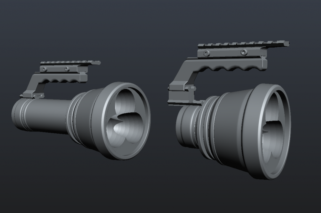
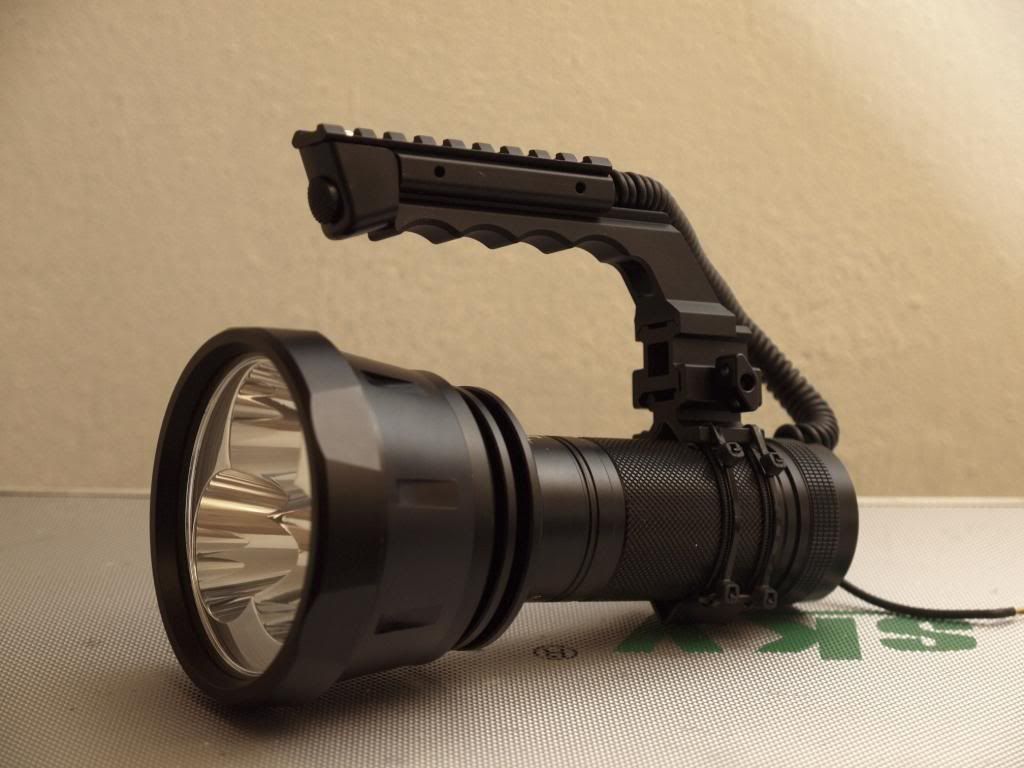
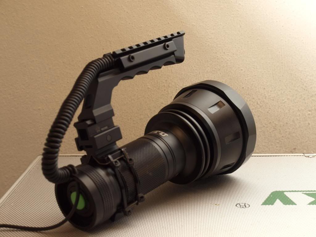
  • BTU Shocker host with 3x MT-G2s on noctigons wired in parallel.
    -Some heatsink improvements if possible i.e Thermal Path from the LED mounting plate to that massive reflector… maybe over a copper gasket that fits between the noctigons?
    -It’s already a very beefy host but anywhere I can add heatsinking mass i.e under the LED mounting plate, I will be.
  • Beefy external belt power pack. Lipo 2S capacity up to 20,000mah
    -Case will be built from an Otterbox 3000
    -Lipos offer lots of capacity and won’t sag much under high drain. Plus I have loads of lipo cells I can salvage from my RC helis for testing before I need to buy anything new.
    -Run on the power pack AND be able to switch back to running it on 2S2P 18650 power at any time. Don’t know if this is even possible until I take a close look at the build of the BTU but this would be great and the best of both worlds.
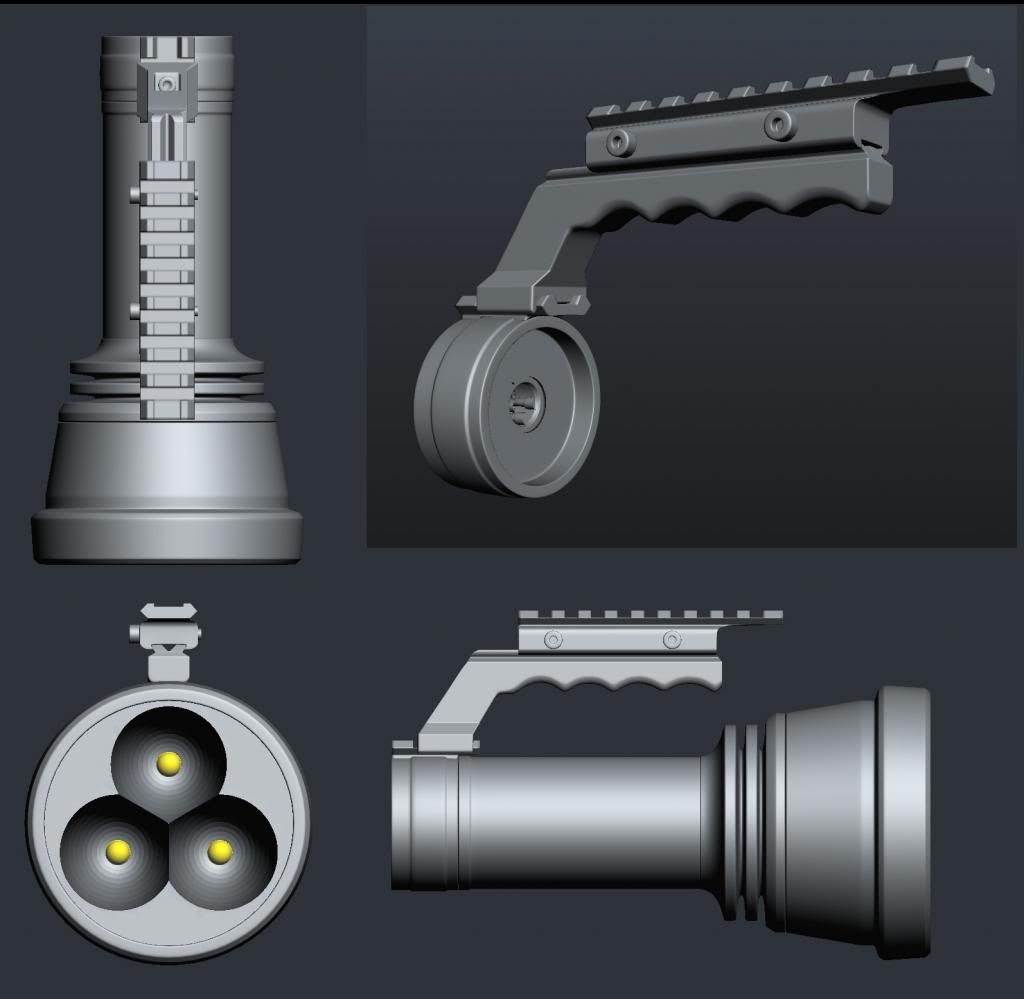
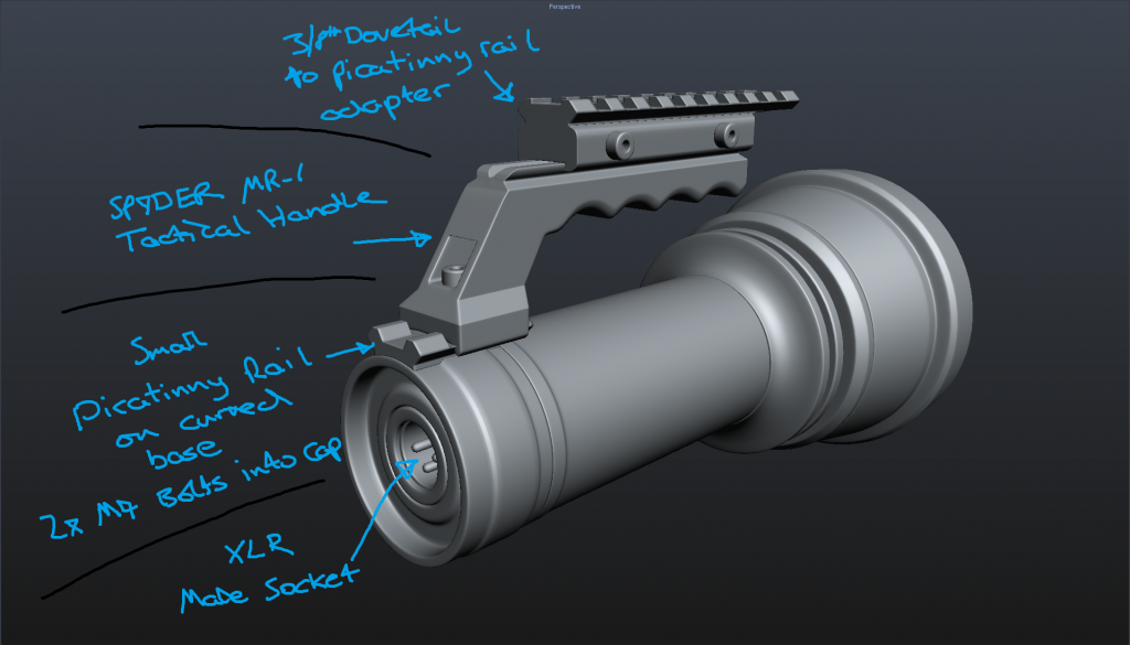
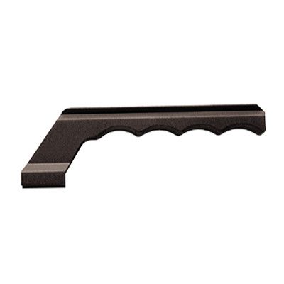
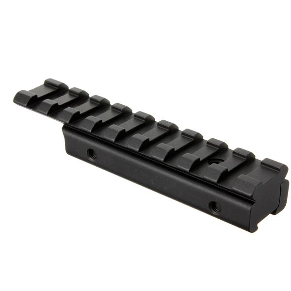
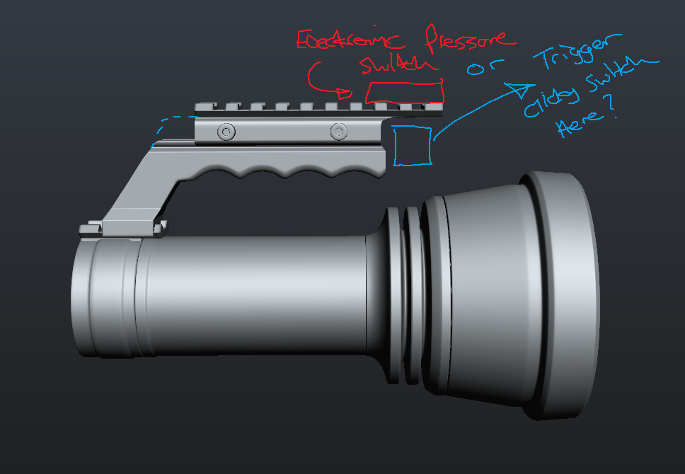
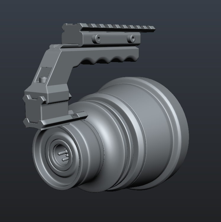
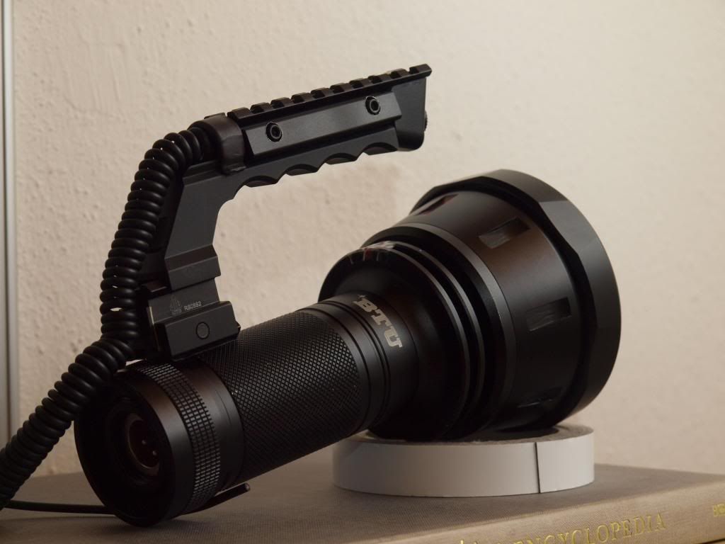
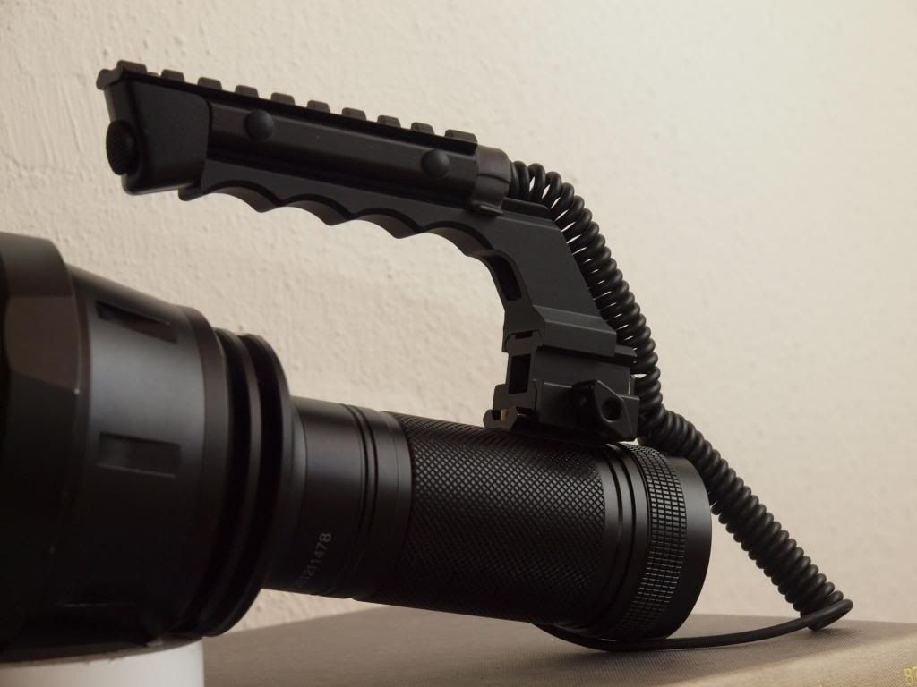
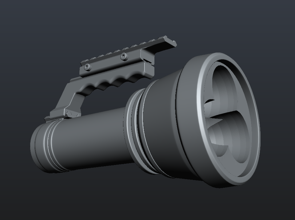
  • I’m a big fan of handles on bulky lights so I will be adding one to the BTU and finding a way of integrating a thumb or trigger clicky switch.
    -I want this light to be usable and somewhat practical as well as being a crazy photo cannon. Intended Tactical application will be finding a very lost cat in a very big and especially dark field :wink:
  • Drivers based on 7135s with MCU modded for >6v, maybe 3 in parallel stacked to high heaven! :slight_smile:
    -Total output on Turbo around the 15A mark…maybe higher if I can justify it/achieve it That should get it close to being a 100W light…right? :open_mouth: …Toasty!
    -Maybe run it with at least 4 modes on a custom programmed Atmel chip to get >5A per emitter on Turbo, 3A each on High and then sensible and usable Mid and Low
    -I suspect I will need to figure out very good heatsinking for the drivers to stop them overheating/melting/throttling back, no idea how hot these will get running at over 6v @ 15A and dissipating the voltage excess of fully charged 2S lipos (8.4v). Lots of testing needed here for sure.

-

OK so that’s the gist of what I’m planning to do and now onto some early progress.

The Power source

So the first thing I started working on, and in fact the only physical thing I can tackle as I wait for parts is the Otterbox 3000 based, belt mounted, Lipo battery pack.
I actually had a used otterbox sitting around that I could butcher for this build and it makes for a very sturdy and spacious host for what I need. Just about perfect in fact.

Here are the components for this part of the build, not all of them to get it finished but enough to get something together.
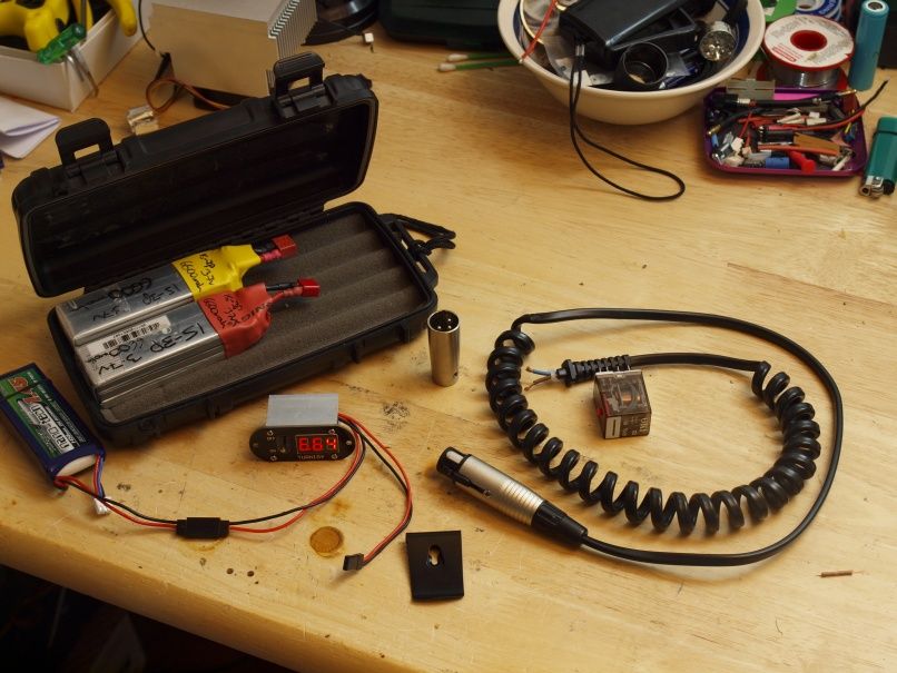
  • Otterbox 3000
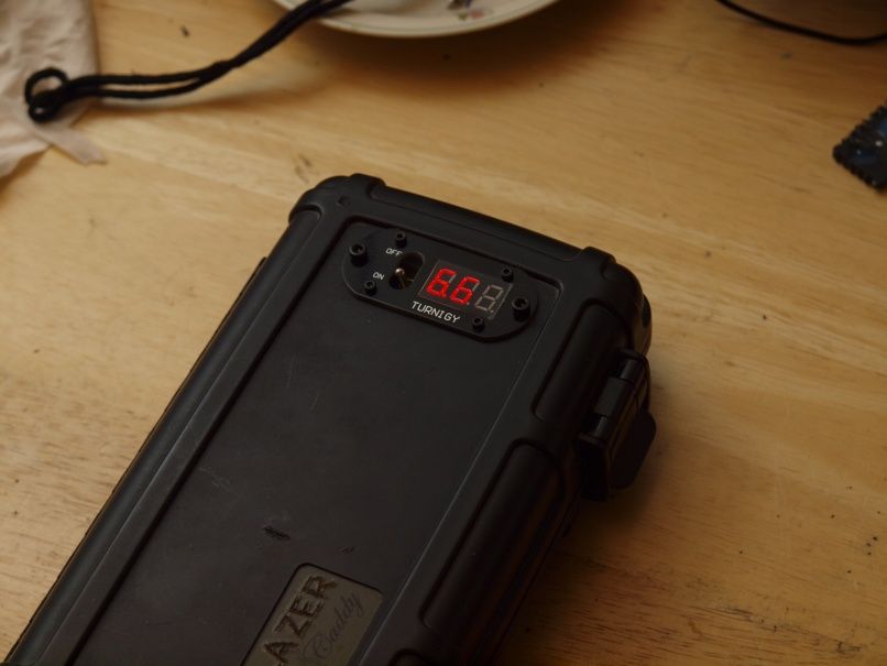
  • Turnigy voltage monitoring panel with integrated power switch. This is a neat little unit that I bought for an RC project but never used due to it’s weight, but it’s exactly what I needed here. This will give me a visual indication of the packs charge level and also function as a master on switch for the pack to send power to the torch.
  • High current switching relay 6v-12A, possibly two in parallel if the current gets too high for one - (not this exact one just used it as a size reference to make sure the actual one will fit). This will be driven by the little master switch on the voltage monitor and send power to the torch or not as required. I will also aim to build in some low voltage protection for this power pack and these relays will automatically cut power when the Lipo charge gets below a certain point.
  • The all important belt clip. This one is pretty undersized but it’s all I had lying around. Need to track down a sturdier one eventually, for now it does the trick.
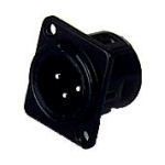
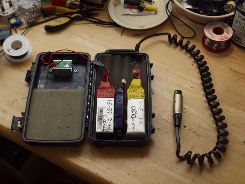
  • Flexi Power cord, it contains 18Awg copper wires and is spiral wound using a dowel and heatgun. This cord will be one of the most crucial parts of the build, resistance losses on such a length of cable could be the real killer of performance if I’m not careful. This cord may change for something better once I do some assembled testing. For now it’s the best balance of weight and wire thickness/tested resistance I had available. The plug on the end is an XLR female 3 pin that I will be using to connect to the torch. There are probably better options available but these are pretty beefy (rated for 15A DC), high quality connectors that have a locking action. They are also about 16mm in diameter so they should play quite nicely with the BTU’s ~17mm switch boot opening. I’ll probably still need to remove some material but it should work.
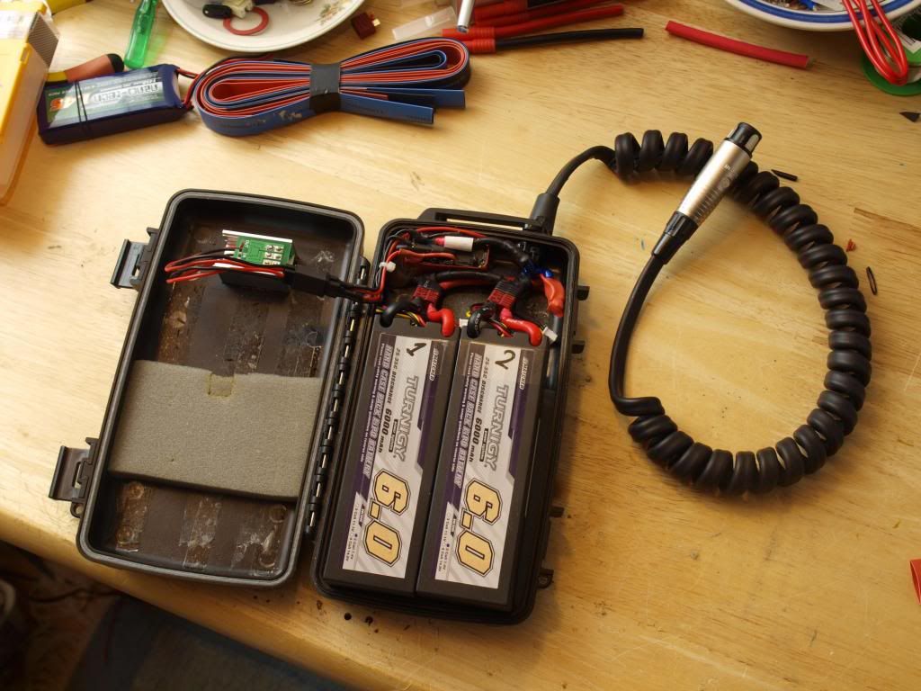
  • 2X homemade 1S-3P 6600mah packs. I converted a couple 3s-1P 2200mah heli lipos to make these and I will be connecting them in series and using them for testing this build. These will ultimately be replace by a set of two or four(max) 2S 5000mah Turnigy lipo packs. Or if I’m being cheap and these packs perform well enough, I’ll convert another two of these 12v packs to 1S-3P and call it good enough at 13200mah capacity. :slight_smile:

Let the dremeling and drilling commence!

Hole cut and Voltage monitor installed. 6.6v displayed because of the 2s LiFePO4 receiver batt I’m using to test the display.
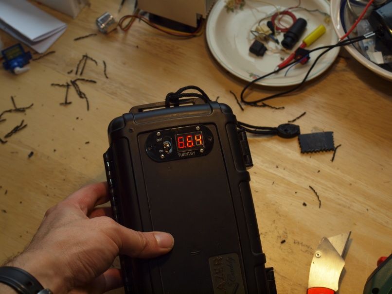
Looks nice

…but the display has some wicked PWM flicker!!! :_( Argh!.

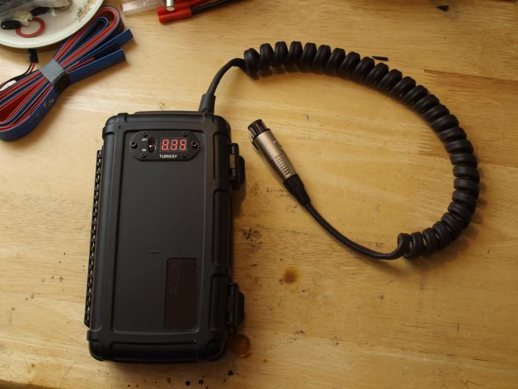
Power cord installed.

Front

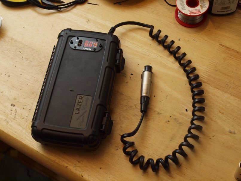
…and back of the assembled piece.

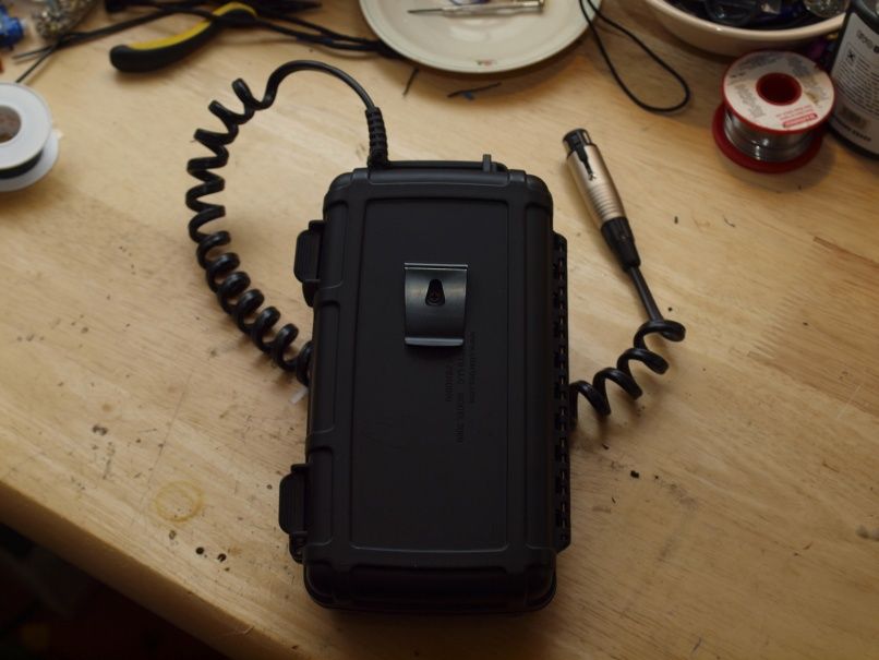
Quite pleased with how it looks and feels on the belt. Balance is pretty good even with those cells mostly down towards the bottom but as I add more wiring and components to the top it’s going to even out more.
Can’t help but feel like I’m using a geiger counter when I’ve got it on and waving the XLR around! :wink:

So that’s the progress so far on the power pack. So far so good and once the relays arrive I can finish it up. In the meantime I’ll ticker away on the circuit and monitoring side of things to see what I can get done. As mentioned above I really need a low voltage cutoff to protect the Lipos and a temperature monitor/alarm would be nice to have for safety.
I am also considering installing a small lipo balance charger so this pack can be plugged into a 12v power supply to charge the packs without needing an external charger. It would probably be more of a novelty as I’d certainly not use it much myself but could be handy in an emergency. I have a few lipo balance chargers that are small enough to fit (just about) but they would take close to 25hours to fully charge this monster pack :stuck_out_tongue:

Well I’ve certainly got enough to keep me busy while I wait for the rest of the parts to arrive. :slight_smile:

Comments really welcome. I’ve probably bitten off way more that I can chew on this project so if anyone has any advice or suggestions please let me know.
Especially if you think there is a better way of doing something or know of a part that you think would be ideal for this project.

Cheers
Linus

Bad boy.

Man, you shoot for the stars… And unlike me, you actually get there. If I attempted this, I wouldn’t even make it off the ground.

hah, we’ll see… there’s SO much that could potentially trip me up on this one I don’t really want to think about it all at once! :stuck_out_tongue:
Step by step. Making a glorified lunchbox is one thing :slight_smile:

Stage two of “Things to do While I wait for the damn postman” is more virtual.

I’ve been busy assembling a shopping list of parts that I need to get to modify the BTU shocker and fit it for a tactical handle as well as make it work with the XLR power jack in place of the tailcap Clicky.
So many variables on this one and not having the actual flashlight in front of me is making planning a lot of this really hard. So again I decided to mock things up in 3D to give me a better sense of how things fit together and what parts I could use and which ones wouldn’t work.

The handle is my favourite part of this build and it only took some time googling the keyword combination of handle, tactical, flashlight and mount to eventually drop into the wonderful world of picatinny/weaver rail mountings and accessories and all the cool potential these systems offer.

As a result I quickly dismissed the commercial handles on the market that were actually designed to be used with flashlights For example this one from Jetbeam Jetbeam Rail Mount and Carry Handle
Not just because they were really very expensive and probably wouldn’t even fit the BTU unmodified but also because I wanted to have more flexibility and the ability to lego something together that would do exactly what I needed.
A big part of having a functional handle on a flashlight for me is being able to operate the modes and power directly with the hand holding the flashlight no stretching around to find a button/collar or having to use a second hand entirely to operate a tailcap clicky. I need a good way of mounting a thumb or trigger style power button on this flashlight and that ment going through a LOT of possible configurations and combinations of accessories to find something that would do the trick.

Many…many hours of googling and ebaying later I think I have found something that will work really rather well. It’s not the most elegant solution but I think it looks pretty cool, should work wonderfully as a handle for the BTU and gives me exactly what I need in terms of mounting space and layout for potential switch options.

Off to the land of 3D to model a scale prototype and see if everything fits as it should :slight_smile:
Note: The BTU and the parts are accurate in scale and most dimensions are precise. But as I am only going off photos I’m doing a lot of filling in the blanks bewteen the measurements that are available so these are good enough to make educated measuring and fitting descisions on but certainly not to CAD/CAM levels of precise. The BTU is accurate where it matters but as you can tell it’s not a particularly true model. It’s basically a 3D sketch to give me an idea if what I ordered actually does what I imagined when assembled in 3 dimensions and attached to the Flashlight.

It also lets me cut twice or as many times as I want and measure only when I’ve messed up enough times to stumble on the right answer ;). Trying this stuff out and making a mistake on the real thing could be a lot more costly!

So here is a look at what I’m hoping to see at the end of this project.

The BTU shocker with tacticool picatinny/Spyder MR-1 rail handle combo.

#

The Ingredients are as follows.

One of these. Spyder MR-1 Paintball marker tactical Rail/Handle Picatinny 22mm rail mount on base and 3/8th dovetail rail scope mount on top.

A touch of this cut down to size and bolted to the tailcap with 2x M4 Bolts. This is the Base rail and if needed allows any picatinny compatible accessories to be mounted securely here instead of the handle.

Mixed in with one of these for that special zing. XLR male socket installed in tailcap for power.

And on top is a thick layer of one of these. This has two functions. It gives the handle more height/width for a sturdier hold and gives me a sizable picatinny rail on top for extremely useful expansion potential like mounting a laser scope… for preciser illumination or something…I don’t know… it’s tacticool! :bigsmile: …and a nice mounting region both above and below for power button options.

These switch mount options are shown below. Still thinking about what could work best. But I’m rather partial to the trigger operated clicky myself.
Or why pick just one, why not a momentary pressure switch mounted via a picatinny bracket (they make these for tactical torches) onto the top for momentary on and a trigger reverse clicky below. Would require some custom driver programming if this is possible at all. But it would be cool…so many options to consider :slight_smile:

Oh and I also have some rubber picatinny protectors coming which should help fill in any unneeded and rather harsh edges of the Rails. Should be pretty comfy to hold then. The angular gap at the back also needs to be filled with something but that shouldn’t be hard fix.

In any case I’ll need to have the parts in front of me and play around with how all this feels in the hand before I can make any more decisions on ergonomics or layout. This at least has reassured me that the parts I cobbled together are compatible and make for a good starting point for a useful handle.

The postman can’t come soon enough! Hehe
Cheers

Sweet mother of god

Very impressive plan and execution to date. Love the look in your renderings. May want to be careful how you handle that thing around police. Looks like it could be mistaken for a weapon other than the photon cannon that it will be. Best wishes and look forward to following your progress.

Orsm Linus. I’m looking forward to your creation. If you find a driver that will run 3 MTG’s give us a holler. While your at it can you lend me some of your drawing skills. Good luck. Cheers.

That is all…

hehe, thanks for the encouragement guys.
Hopefully it won’t take too long to get this project up to a functioning state. I’m at the mercy of an unusually hit and miss chinese postal system at the moment as I’m sure you all know :slight_smile:

One thing I wanted to ask, is it at all possible to fit 4 18650s into a stock BTU battery tube? I don’t mean using the stock carrier but just whether they would fit inside the tube without having to enlarge it. By my calculations using the 50mm outside diameter quoted on the site and tube thickness of 4.45mm from a great review by “the” here on this forum (would be lost without that review btw) I should have just enough space to squeeze 4 cells in there. If anyone has a BTU shocker and would be willing to test the fit for me that would be awesome!

The reason I’m curious is that ideally I’d love to be able to run this light on either the battery pack or 4 18650s in 2s2p config depending on the situation. First hurdle to that would be the four cells actually fitting the tube, then making a new carrier for them, giving up all that lovely empty space inside and cramming the XLR socket extra tight into the tailcap. Not to mention making my driver wiring life a lot more difficult.

So please someone tell me that the cells fitting the tube is a pipe dream and allow me to make this a power pack only light! :wink:

Cheers

Much as I would like to see that portion of the build, 4x18650s will not fit in a standard tube. Anyway the tube might not be empty 4 long, space to fit heatsinked drivers and pos lead to balance it, and a fan for cooling >) :wink:

45.0 mm inner diameter on the threads - 4 bare Sam 20Q's don't fit. The Vostro that takes a 4 cell carrier is 45.7mm inner diameter. So, the Shocker is really, really close but NG.

Damn… so close, cheers for having a look.
I guess the only option would be to ream it out a bit but it’s probably not worth the extra hassle.

You’re right xmint the space inside probably won’t be going to waste and certainly will give me many more options for assembly. Exploring active cooling options is certainly something I’ll be doing but hopefully I won’t have to add any extra lead weight for balance purposes. The XLR plug from the power pack alone weighs over 50g and it along with the fairly heavy cord hanging off the back of the BTU should be enough to balance out that heavy front end.

With regard to the tail cap on the BTU, to get at the rubber boot you have to screw out the center part of the back end with the 4 dimples right? I assume the inside of the cap is a solid piece plate with only a hole in the middle for the switch boot to pass through. Is this tailcap easy enough to disassemble or is the thing glue shut?

Cheers

Be very careful.

One thing I immediately noted was the use of an XLR for power.
I've seriously never ever seen an XLR being used for anything but low current signal-only transfer.
Yours might be different with the 15A rating and all, or yours might melt and cause shorts, fire and explosions.
If you're going for 100W from a 2S config, you'd be cutting it close to your rating.
If it were my project, I'd use XT60s or speakONs.

Batteries. Two homemade packs in series doesn't raise any alarm bells?
Single blocks will reduce headache immensely in the future.

You could possibly shorten the whole thing by a significant portion if you increase the drop from the rail.

In the end, it's your project, your call. Just throwing some suggestions out there.

All the best!

Thanks for the comments and you make some very good points.

Regarding the XLRs I believe they used to be implemented for high current power supply for speakers and such but not anymore. I only know I had some available, saw the 15A rating and felt the contacts and internals were reassuringly robust to back up that claim. No doubt a 15A rating and running it at the kind of currents I intend is cutting it fine so I appreciate you suggesting the SpeakOn connectors. Those look superb and exactly what I need. Will be ordering a couple to have a play around with. They may even make installation in the BTU easier since they are sightly narrower than the XLRs. :slight_smile:

The packs look dodgy but they are in no way less safe than ones bought pre assembled. I’ve been building custom packs from individual cells quite a bit for very high drain Heli use and have never had a problem, as long as you’re careful to ensure no bad cells with different IRs end up in the mix and you regularly keep an eye on the health of each cell they will function just as safely (or dangerously depending on your view of Lithium technology ;)) as anything factory assembled.
That said these packs are only really intended for testing as I’ll be replacing them with a set of 2 or 4 of these at some point.

Still when dealing with lithium cells it’s best to be safe than sorry, and there’s a reason I want to build a temperature monitor/alarm into the pack and insist on having a quick disconnect power plug on the flashlight :stuck_out_tongue:

I’m not sure I understand what you mean with shortening the whole thing by increasing the drop from the rail. Can you elaborate?
Edit: Oh I think you meant removing the body of the BTU entirely, raising the handle higher and screwing the tailcap directly into the head. Right? That could be interesting. I hadn’t contemplated this till now because I was still hoping I could make this flashlight work on both Pack and 18650s but if that’s out of the question this may be something to try.
Not sure if the tailcap would thread all the way onto the head, BTU owners, would this be feasible?

Thanks again for the comments
Linus

Had to try it! :slight_smile:

Yep it’s hilarious…this must be attempted! :slight_smile:

The improvised riser is not based on something that exists in the real world but I’m sure I could find something that would fit the bill :slight_smile:
Edit: Something like this would work perfectly

Picatinny Riser 25mm

…and with an appropriate spacer it ever looks somewhat nicely proportioned!

What I really meant was placing to unprotected packs in series is quite iffy to us battery snobs. :)

Nice modelling work, btw!
I'm sure it's possible, if the spacer is designed correctly, for your BTU to still function as a 18650 flashlight. :)

Thinking about it, though the tube in standard form will not take a 4 cell carrier if you had machining facilities it could be made to do so.

The end cap from a FF4 fits the Shocker In fact the shocker’s battery tube is slightly bigger in diameter, so I would think that even after machining there should be enough metal left for reliability as there is in the FF4.

If the socket, plug and lead does balance the head that will be a bonus.

If you go down the active cooling path be interesting to see which way you go. I have been looking at a sandwich peltier and annular fan for one of my projects (a 47 yo space beam torch updated slightly LOL).

Yeah I wish I had the tools and the ability to machine, would make things a lot easier alright.

Another question for the BTU owners. If you thread the tail cap as far as it will go onto the head of the light i.e eliminating the battery tube entirely. How much of a gap is left to fill between the head and the front of the tailcap?
Assuming you can’t screw the cap on all the way because of that long threaded section on the head.

Peltier coolers are definitely fascinating. Maybe I can figure out some way of making one work here.

Cheers

I’m using an XLR plug in conjunction with a 13.1V LiPolymer pack to power an older Canon 1DsMkII camera that had a NiMH pack. The OEM pack is unreliable with some age on it, my external pack will run the camera for several days.

Of course, I’m not pulling the amps you’re looking at, but I’ve no issues with the plug whatsoever.

Nice work, love the renditions, can’t wait to see what you actually do. One of those would be fantastic in the Photography profession, on location lighting extraordinaire!!! :slight_smile: