I put the board for my 20mm Nanjg compatible driver up on OSHPARK.COM’s project sharing site. You can order bare boards from them for around $3 for 3 boards…
All the passive components are 0805 size for easier hand assembly. You can use any Nanjg compatible firmware (Nlite, BLF-VLD, Dr Jones specials, etc).
I have built up several of these boards and they all worked fine the first time…
Just to clarify this from a electronics noob who has studied the layout for.... 22 seconds? But I can take what I need from an existing nanjg driver right? I don't mean the Attiny or AMC but all the others should be fine..? Or I need to order different sizes for this??
BTW, you can get Kapton solder paste stencils from OSHSTENCILS.COM for cheap. Their quality is top notchs. I sent them a test pattern with …2 mm features on it and it came out perfect. Just upload the Eagle .BRD file to them, select what you want, Paypal them a few bucks, voila.
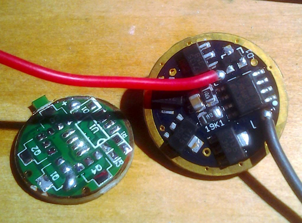
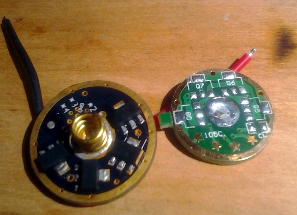
I solder paste the spring side first (it just has 4 AMC7135’s on it), place components, reflow the board in my oven (DIY Reflow Oven), flip the board, paste the CPU side, place components, then reflow the board again.
Pasting the second side can be a little tricky since the board+components on the now bottom side makes the top side no longer sit flush with my solder pasting board holder. The board is small and simple so I had no problems just hand holding/aligning the stencil. It might be easier to do the CPU side first since that side has more/finer parts on it.
You might be able to make the Nanjg parts fit on the board, but they are smaller than the 0805 sized ones ones that I used. It looks like they may be big enough to span the pad spacing that I used. The reverse polarity diode is in a different package, but the Nanjg diode might be able to fit over the BAT54 pads.
One of the resistors that I am using is an 0603 package… Mouser sent me the wrong ones. I think the Nanjg parts are 0402 packages… even smaller.
Thank you guys. I have just been googling around to find out about all these sizes and other stuff related to it. Seems if I buy from one of the name brand suppliers I'll have to build 100 to get reasonable prices on components. I'll have to see what the ebay can offer I guess. but right now its off to bed :-)
Diode D1 is a BAT54 (be careful of the different versions with various diode arrangements). What do you mean different versions? Got a link to Mouser or preferably Digikey? Will the ones below work??
The BAT54 series of diodes can contain one or two diodes in the package. The difference is in how the diodes are connected differently. The board is laid out for a plain BAT54. A BAT54-C or even a BAT54-S could be used. The BAT54-A won’t work… the diodes are backwards (you could bodge the -A chip onto the board if you had to). BTW, the way my SRK driver is laid out the BAT54-S won’t work there… unless you clip off a pin.
I once bought some BAT54’s off of Ebay… got shipped some unmarked BAT54-A chips… grrrr…
Has anyone measured the voltage drop of this diode vs. the one normally found on the 105C? I'm wondering if this change significantly affects what the MCU is reading. There is a ton of variation anyways in these drivers but I am curious.
Well I guess I can leave my flashlight running on STAR V1.1 and see what the shutdown voltage is…but I haven’t put a multimeter on the pins either…it’s a zener so it should drop .3 or .7vdc thru a diode correct
The one I put together is happily running in a SH98 (clone) from FT, but I haven’t run it down or used it too terrible much either
The BAT54 is a Schottky diode with around 0.2V drop at the currents the CPU pulls. I have seen 105C’s built with Schottkys and with silicon (0.6V drop) diodes.
Not sure what happened…but the rebuild quit working
Not sure if the kid dropped the battery in backward and killed the diode or what…but will no longer light up
Tested with a battery straight to the emitter, it will light, but will not run the ATtiny or modes at all
Either I have to remove/replace the diode or jumper across it, the ATtiny flashes (I put NLite on there just in case the STAR V1.1 got corrupted or something but still no go on the modes or even come on)
Gonna have to do some troubleshooting and figure out what is going on with this…works like a champ though…not sure why it stopped working…uggh! [then to top it off my SRK 7135 driver doesn’t turn all the way off…I’m getting my butt kicked by these drivers…arrrgh!]
Measure the voltage from ground to each side of the diode, if you have voltage on one side but not the other the diode's dead. Or you can just pinch the two diode terminals with tweezers, like a temporary jumper.
Changed the reverse polarity diode to the stock diode that comes from a regular Nanjg 105C, this way you don’t need a special 3 lead SOT-323 type diode, the stock one and/or the ones from the digikey shopping cart (from the oshpark projects thread) will work fine
Cleaned up some traces, thickened the signal trace a bit, a few minor fixes is all
Updated the component footprint to that of the 7135 (makes it look a little bit neater on the board)
Added an off time cap pads in 0603 (0805 components will fit, the solder pads will be equivalent to an 0805 high density footprint)
Updated the C1, R1 and R2 to the above 0603 footprint to help out with the spacing between the components
Added SOD-323 diode instead of the SOD-123
Added a 20mm routing ring around the board
All in all it’s the same exact thing he created I just put a little bit of fine tuning on it